Analysis And Simulation Of Single Phase And Two Phase-PDF Free Download
1 Simulation Modeling 1 2 Generating Randomness in Simulation 17 3 Spreadsheet Simulation 63 4 Introduction to Simulation in Arena 97 5 Basic Process Modeling 163 6 Modeling Randomness in Simulation 233 7 Analyzing Simulation Output 299 8 Modeling Queuing and Inventory Systems 393 9 Entity Movement and Material-Handling Constructs 489
I Introduction to Discrete-Event System Simulation 19 1 Introduction to Simulation 21 1.1 When Simulation Is the Appropriate Tool 22 1.2 When Simulation Is Not Appropriate 22 1.3 Advantages and Disadvantages of Simulation 23 1.4 Areas of Application 25 1.5 Some Recent Applications of Simulation
Engineering Analysis with SolidWorks Simulation 2012 33 Once Simulation has been added, it shows in the main SolidWorks menu and in CommandManager. Figure 2-3: Simulation tab is a part of the SolidWorks CommandManager. Selecting Simulation tab in the CommandManager displays Simulation menu items (icons).
Engineering Analysis with SolidWorks Simulation 2011 34 Before we create the FEA model, let's review the Simulation main menu (Figure 2-4) along with its Options window (Figure 2-5). Figure 2-4: Simulation main menu Simulation studies can be executed entirely for this menu. In this book we will mainly use the main menu to access Simulation .
Simulation Results and Analysis . We set the power frequency to 60 Hz and 100 Hz, respectively. . simulation experiments and research, based on the Matlab/Simulink simulation tool, the simulation model of the three-phase . Simulation Design of Variable Frequency Speed Regulating System for Automobile Remanufactured Generator Test Bench .
Simulation Models and Analyses Reference Version (v1.6) Apr 21, 2008 1 This reference details the simulation models and circuit simulation analyses and describes some simulation troubleshooting techniques. Simulation Models The Altium Designer-based Circuit Simulator is a true mixed-signal simulator, meaning
Simulation data management Simulation-specific data, document, record and content management Simulation-specific product structure Integration with the product & engineering bill of materials, including the management of configurations and variants. Simulation change and process management Revision/version control. Simulation visualization
Simulation is a process of emulating real design behavior in a software environment. Simulation helps verify the functionality of a design by injecting stimulus and observing the design outputs. This chapter provides an overview of the simulation process, and the simulation options in the Vivado Design Suite. The process of simulation includes:
I Introduction to Discrete-Event System Simulation Chapter 1 Introduction to Simulation 1.1 When Simulation 1s the Appropnate Tool 1.2 When Simulation 1s Not Appropriate 1.3 Advantages and Disadvantages of Simulation 1.4 Areas of Application 1.5 Systems and System Environment 1.6 Co
4.5 Simulation result for BD generator output system for case one. 78 4.6 Simulation result for BD generator output system for case two. 79 4.7 Simulation result for MT output for case one and two 80 4.8 Simulation results of Surrette battery for two cases. 82 4.9 Simulation data of converter components for two cases. 83
IEC 61850 Test Simulation Features (Edition2) Test set publishes GOOSE msgs with Simulation flag true DUT with Simulation true will Start accepting messages with Simulation flag true Reject messages from real IED with Simulation flag false true Goose1 Simulation true 2018 Doble Engineering Company. All Rights Reserved 12
n Simulation and embedded system design ufunctional simulation uperformance simulation ŁPOLIS implementation Łpartitioning example uimplementation simulation Łsoftware-oriented Łhardware-centric n Summary Cycle-based, logic simul. Design flow Behavior capture Mapping (partitioning) Architecture capture Functional simul. Architecture simul .
Solutions Manual Discrete-Event System Simulation Fourth Edition Jerry Banks John S. Carson II Barry L. Nelson David M. Nicol January 4, 2005. Contents 1 Introduction to Simulation 1 2 Simulation Examples 5 3 General Principles 19 4 Simulation Software 20 5 Statistical Models in Simulation 21 6 Queueing Models 36 7 Random-Number Generation 44 8 .
simulation grid cells. Figure 6 shows the distribution of upscaled geology, compare with Figure 4. This downscaling and upscaling process is repeated for each flow simulation grid network. Flow simulation is performed using the upscaled geology on each of the 15 flow simulation grid networks. A single 500m long well pair is used.
Why analysis of simulation output ? . Simulation and Modeling / [Chapter 7 ]Nipun Thapa . 28 . Fig: Mean wait time in M/M/1 system for different sample size . https://genuinenotes.com. Simulation Run statistics . Consider a single server system in which the arrival occurs / .
The simulation-based optimization is an emerging field which integrates optimization techniques into simulation analysis. The primary goal of simulation-based optimization is to optimize the performance of a system through simulation. More specifically, it is a way to find the optimal set of parameters for a given criterion. Then the opti-
CS445: Basic Simulation Modeling!!! Travis Desell!! Averill M. Law, Simulation Modeling & Analysis, Chapter 1. What is Simulation? A simulation uses a computer (or computers) to evaluate a model numerically, and data are gathered in order to estimate the desired true characteristics of the model. 1.
SOLIDWORKS SIMULATION GET ENGINEERING INSIGHTS WITH VIRTUAL SIMULATION SOPHISTICATED SIMULATION IS NO LONGER JUST FOR SPECIALISTS Concurrent Engineering for more informed design SOLIDWORKS Simulation gives product engineers access to powerful FEA (Finite Element Analysis
Simulation modeling methodology research and simulation analysis methodology research have evolved into two near-ly separate fields. In this paper, ways are shown how simu-lation might benefit from modeling and analysis becoming more closely integrated. The thesis of this paper is that si-mulation analysis and simulation modeling methodologies,
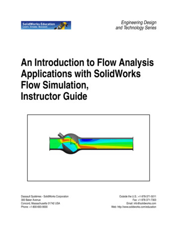
SolidWorks Flow Simulation Instructor Guide 3 SolidWorks Simulation Product Line While this course focuses on the introduction to flow analysis using SolidWorks Flow Simulation, the full product line covers a wide range of analysis areas to consider. The paragraphs below lists the full offering of the SolidWorks Simulation packages and modules.
System Assembly and Modeling (SAM) in CST Studio Suite allows simulations to be combined into a single 3D model or a linked automatic workflow, and the Hybrid Solver Task allows multiple solvers to be combined in a single simulation task. SIMULATION Industrial Equipment: EM (left) and thermal (right) simulation of a microwave oven in use.
ior and achieving simulation of the behavior in real time. Categories and Subject Descriptors: I.6.5 [Simulation and Modeling]: Model Development— Modeling methodologies General Terms: Simulation, Graphics, Dust Additional Key Words and Phrases: Physically-based Modeling, Real-time Simulation, Vehicle, Particle Systems, Computational Fluid .
Simulation Project Success and Failure: Survey Findings. Simulation and Gaming, 33(1), 49-66. Ruben, B. (1999). Simulations, games, and experience-based learning: The quest for a new paradigm for teaching and learning. Simulation & Gaming, 30, 498-505. Nursing Cant RP, Cooper SJ. Simulation-based
models and types of analyses available using Altium Designer's Mixed-Signal Circuit Simulator. This reference details the simulation models and circuit simulation analyses and describes some simulation troubleshooting techniques. Simulation Models The Altium Designer-based Circuit Simulator is a true mixed-signal simulator, meaning that it can
1.2 Multidisciplinary Aspects of Simulation 8 1.3 Models 11 1.4 Deterministic and Stochastic Simulations 14 1.4.1 An Example of a Deterministic Simulation 16 1.4.2 An Example of a Stochastic Simulation 17 1.5 The Role of Simulation 19 1.5.1 Link Budget and System-Level Specification Process 20 1.5.2 Implementation and Testing of Key Components 22
NX Design Simulation NX Motion Simulation Ask "what-if" and compare your options in the design process NX Advanced Simulation Intelligent model generation, industrial strength productivity, multi-physics, multi-disciplinary Best Practice Wizards Extends the value of simulation to new and infrequent users NX Nastran
HDL Verifier [4] is a co-simulation framework produced by Mathworks which pairs a Matlab-based software model with an RTL simulation. In this pairing, the software model generates stimulus to input into the RTL simulation, and performs checks on the output from the RTL simulation. The framework also supports reading to and writing from registers,
1. Click the Simulation tab and New Study. Under General Simulation click Static. 2. In the simulation tree the mechanical body is labeled WeldedCorner, right click on that and select Apply Favorite Materials Plain Carbon Steel. 3. Right-click on Fixture in the simulation tree and select Fixed Geometry. While in the
line to line voltages. In the simulation have to mention the a continous (powergui) block and also mention required parameters in the MATLAB before the executing the simulation. In the simulation Runge katta method is used for the simulation of SPWM and type is fixed-step There are several techniques of Pulse Width Modulation (PWM).
Modeling and Arena MANUEL D. ROSSETTI University of Arkansas WILEY John Wiley & Sons, Inc. Table of Contents 1 Simulation Modeling 1.1 Why Simulate? 2 1.2 Types of Computer Simulation 3 1.3 How the Discrete-Event Clock Works 5 1.4 Randomness in Simulation 9 1.5 Simulation Languages 9
Transients (EMT), power systems modeling & simulation, and . First, real-time simulation is defined. An overview of the evolution of real-time simulators is then presented. Two other essential questions are then answered. Why is real-time simulation needed? Where does real-time simulation fit best? Finally, this paper concludes
If Flow Simulation is not available in the menu, you have to add it from SOLIDWORKS menu: Tools Add Ins and check the corresponding SOLIDWORKS Flow Simulation 2017 box under SOLIDWORKS Add-Ins and click OK to close the Add-Ins window. Select Tools Flow Simulation Project Wizard to create a new Flow Simulation project. Enter Project name:
1. Can formal simulation aid in designing effective road tests for AVs? By formal simulation we mean simulation-based testing that is guided by the use of formal models of test scenarios and formal specification of safety properties and metrics. More specifically, do unsafe (safe) runs in simulation produce unsafe (safe) runs on the track?
network simulation, network emulation, NS3, discrete-event simulation, simulation credibility, model validation 1. INTRODUCTION Over the last decade network simulation has become increas-ingly important. One reason for that is the rapid growth of the Internet and networks in general. Therefore new potent
(a) HAAS dual system control simulator hardware. (b) Swansoft CNC simulation software showing machine control panel simulation for HAAS control. (c) Swansoft CNC simulation software showing machine control panel simulation on a tablet pc for Fanuc control. (d) VERICUT CNC machining and program verification software (e) VERICUT CNC on
ism [15] and a visual Agent simulation based on a 3D real-time visualization simulation in real-time. The visual agent simulation allows us to visualize the land combat simula-tion scenarios in a 3D scene. We also propose to reduce the programming time consumed to develop or modify the sce-nario tactics for combat in real-time visual simulation by us-ing Cell-DEVS, which allows us to use .
simulation system state via direct computing, yet without loss of simulation accuracy. As the traditional discrete event network simulator (such as NS[4]) obtains all the changes of simulation system state via discrete events, this method can cut down the number of discrete events and reduce the simulation running time compared with the
2.2.1 Direct numerical simulation of homogeneous turbulence decay The simulation of de Bruyn Kops (UW, 1999 PhD thesis) is the rst successful direct numerical simulation of homogeneous turbulence decay. It is useful to see what is involved in performing this simulation. Start by assuming that the velocity eld u(x;t) and the pressure eld p(x;t)
dynamics simulation [28]. On this basis, the molecular dynamics simulation was the carried out. To determine the glass transition temperature before and after modification, a temperature range of 200-650 K was selected for the simulation, with every 50 K a target temperature. The molecular dynamics simulation of each target temperature was .
sion system integration layer [3, 4]. The simulation of water-shed 3D visualization simulation is the basis of constructing digital watershed visualization information platform. The key part of 3D visualization simulation system is the estab-lishment of watershed professional model in the basin and the simulation of terrain virtual scene [5, 6].


