Automatic Camera And Range Sensor Calibration Using A-PDF Free Download
2-9V in unit & 2 AA in camera. Match polarities ( ) and ( ). Set camera date back, close camera lens and connect plug to camera port. 2 3 Secure camera, open camera shutter, and slide unit power switch to (ON) and back to (OFF), then push camera test button. Close camera Shutter, remove camera & load film, connect plug to camera, close cover. 4
ZigBee, Z-Wave, Wi -SUN : . temperature sensor, humidity sensor, rain sensor, water level sensor, bath water level sensor, bath heating status sensor, water leak sensor, water overflow sensor, fire sensor, cigarette smoke sensor, CO2 sensor, gas s
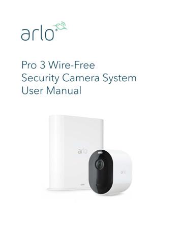
User Manual Replace a Pro 3 Camera battery You can leave the camera housing in place so the camera position stays the same. 1. Release the camera from the camera housing. Press the button on the charging port underneath the camera. The camera clicks as it disengages from the camera housing. 2. Pull the camera all the way out of the camera .
Laser Sensor Microphone Sensor Projectile Sensor Valve Sensor Photogate Sensor Motion/Distance Sensor Camera Shutter Sync Sensor Clip Sensor Multi-Flash Board 2. . Camera Axe 5 in a much cheaper package for the DIY/Maker crowd. Hardware The top of the both versions has a display screen, a number of buttons, a power switch (not on shield .
Laser Sensor Microphone Sensor Projectile Sensor Valve Sensor Photogate Sensor Motion/Distance Sensor Camera Shutter Sync Sensor Clip Sensor Multi-Flash Board. . Camera Axe 5 in a much cheaper package for the DIY/Maker crowd. Hardware The top of the both versions has a display screen, a number of buttons, a power switch (not on shield
WM132382 D 93 SENSOR & 2 SCREWS KIT, contains SENSOR 131856 WM132484 B 100 SENSOR & 2 SCREWS KIT, contains SENSOR 131272 WM132736 D 88 SENSOR & HARNESS, contains SENSOR 131779 WM132737 D 100 SENSOR & 2 SCREWS KIT, contains SENSOR 131779 WM132739 D 100 SENSOR & 2 SCREWS KIT, contains SENSOR 132445 WM147BC D 18 RELAY VLV-H.P.-N.C., #WM111526
On power-up, the camera interface board will read the SW1 DIP switches and set the camera video mode accordingly. If the DIP switches are set for 'Default Camera Mode' then the camera (and camera interface . Serial Camera Control The camera may be controlled by serial VISCA commands (J3). The VISCA serial signal is routed through the .
1. Place the outdoor mount and secure it with screws. For drywall, use the wall anchors we provide. 2. Release the camera from the camera housing. Press the button on the charging port underneath the camera. The camera clicks as it disengages from the camera housing. 3. Pull the camera all the way out of the camera housing. 4.
Camera CCH-01G Jeep Grand Cherokee Camera CMB-16G Mercedes Benz GLK Trunk Handle Camera CCH-01S Jeep Wrangler Spare Tire Mount Camera CVW-07L VW Beetle License Plate Light Camera (LED) CVW-07G VW Beetle License Plate Light Camera CFD-03F Ford Tailgate Handle Camera CCH-01W Jeep Wrangler License Plate Light Camera CBM-01T BMW 5 Series Trunk .
Get to Know Your Essential Series Camera 6 Arlo Essential Series ire-Free Camera User Manual Meet your Essential Camera Your camera includes an integrated battery that can’t be removed. Front view Rear view Bottom view Sync button Charging port cover Camera LED Screw mount hole Microphone Ambient light sensor Speaker Camera lens Weather resistant
4. Sensor Settings pane—Set the sensor parameters in this pane 5. Status bar—Shows whether the sensor is connected, if a software update is available, and if the sensor data is being recorded to a file 6. Live Sensor Data controls—Use these controls to record, freeze, and play real-time sensor data, and to refresh the sensor connection
A sensor bias current will source from Sensor to Sensor- if a resistor is tied across R BIAS and R BIAS-. Connect a 10 kΩ resistor across Sensor and Sensor- when using an AD590 temperature sensor. See STEP 4 Sensor - Pins 13 & 14 on page 8. 15 16 R BIAS R BIAS-SENSOR BIAS CURRENT (SW1:7, 8, 9, 10)
SENSOR STATUS SENSOR BYPASS Press to bypass, press again to re-enable GREEN Sensor is dry RED Sensor is wet Red light indicates sensor is bypassed RAIN SENSOR BYPASS Blue/White wires to normally closed sensor terminals Orange/White wires to normally open sensor terminals 2 3 5 6 4 1 5 Wireless Rain
Camera Modules 6 Image sensor board Serializer board FAKRA connector Coax Cable 2Mp camera module AR0231AT 2.3 Mp 1/2.7" CMOS image sensor MAX96705 GMSL Serializer 8Mp camera module (TBD) AR0820AT 8.3Mp 1/2 inch CMOS image sensor MAX9295 GMSL2 Serializer Optimized for low light and high dynamic range scene performance
activities such as syncing the camera and updating the camera firmware. See the following table for explanations for the Camera LED. Camera LED Color and Action Meaning Solid blue The camera is connected to the Quick Charge 9v power adapter and is fully charged. Fast blinking blue for 3 seconds The camera is connected to the Quick Charge 9v power
3.1.2 Camera/Vision Camera/Vision tab in the Ribbon Menu contains camera controls and is available only when MV module is installed and at least one camera is enabled in the settings. Camera/Vision tab, when two cameras are enabled In the Camera/Vision tab there are following tool groups: Selected Camera.
Camera LED Light An integrated LED light is located in the main housing of the camera. The light switch is located on the right of the main housing which turns the light on and off. Rotating the Camera The camera automatically loads the last zoom and color setting depending on the rotation of the camera. 1 Self-view Camera rotated directly at user
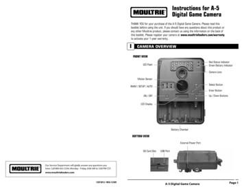
face the camera down the trail tilted at a slight downward angle. Face the camera North or South to avoid over exposure from the sun. Clear brush away from camera front to avoid false triggers from the wind. A-5 Digital Game Camera Page 9 Camera Setup Battery Installation Open the camera cover and install 4 C-Cell Alkaline batteries. Make sure .
5 Custom camera insert* 6 KODAK CRV3 Lithium Battery or equivalent** (not shown) 7 User's Guide or CD, Software CD, and Quick Start Guide (not shown) NOTE: *The custom camera insert perfectly fits your camera to the optional KODAK EASYSHARE Camera Dock II. DO NOT DISCARD. ** If your camera was packaged with a KODAK EASYSHARE Camera
2 Installation Guide Introduction Product overview This is the installation guide for TruVision Series 4 IP camera models: TVC-5401 (2MPX IP box camera) TVC-5402 (3MPX IP box camera) TVC-5403 (5MPX IP box camera) TVB-5401 (2MPX IP bullet camera, 2.8 to 12 mm) TVB-5402 (2MPX IP bullet camera, 8 to 32 mm)
Viper Digital Cinematographic Camera Operator's Manual The Viper FilmStream Camera combines two different application concepts in a single camera. By selecting the operation mode, the camera operates either as a HD video camera or as a digital film camera. The digital film camera mode is known as the FilmStream mode. Using this manual
f p r r r f p r r r r X Y rrZ X Y Z Ground plane Camera 3D world z Origin at world coordinate Camera Projection (Pure Rotation) X C 1 R W Coordinate transformation from world to camera: Camera World 3 C C W 3 ªº «» «» «» ¼ X X R X r r r r 1: world x axis seen from the camera coord. r1r2 r 3 r 2: world y axis seen from the camera .
camera after a specific period of time that your camera is left idle. The Auto Power Off settings can be set from the Auto Power Off settings menu. Changing Camera Mode Your camera has three main modes: 1) Photo Capture Mode - Use this mode to capture photos with your camera. 2) Video Capture Mode - Use this mode to capture videos with your camera.
training. Responsibility for the safe operation of the vehicle remains with the driver at all times. The camera bracket is attached to the windshield, and the camera snaps into it. (See Section 3.1) Camera Lens Radar Sensor Camera Figure 1 – Bendix AutoVue FLC-20 Camera Figure
CSI Camera Module 5MP OV5640 Datasheet 1. Introduction The CSI Camera Module 5MP OV5640 is an add-on board for the Apalis computer-on-module which uses MIPI-CSI Interface. The CSI camera module uses OmniVision OV5640 camera sensor with built-in auto-focus. The OV5640 image sensor is a low voltage, high-performance, 1/4-inch 5 megapixel
RG Firearms Range Building STO Range Storage Building F1 Firearms Range 1; 50 Yard Paper Target Range F2 Firearms Range 2; 25 Yard Paper Target Range F3 Firearms Range 3; 50 Yard Paper Target Range F4 Firearms Range 4; 50 Yard Paper Target Range RAP Rappel Tower F5 Firearms Range 5; 200 Yard Rifle Range F6 Firearms Range 6; Tactical Entry House
VER-D2R1-1 DINION capture 7000 PAL license plate camera, 3.8 to 6.4 m range, with day/night overview camera Order number VER-D2R1-1 VER-D2R2-1 DINION capture 7000 PAL license plate camera, 5.5 to 9.1 m range, with day/night overview camera Order number VER-D2R2-1 VER-D2R3-1 DINION capture 7000 PAL license plate camera, 7.9 to 13.7 m range, with
Piezo Haptic actuator Flux-gate Currentsensor Proximity Sensor Humidity Sensor 6-axis Motion Sensor 7-axis Motion Sensor 9-axis Motion Sensor 6-axis Motion Sensor with DMP Rotary Encoder TMR Angle Sensor Varistor Buzzer Noisefilter For Audio MEMS Microphone Lens Actuator Ag-stacked Film - 5-
May 23, 2017 · sensor. Since US list price for both sensors is similar, use of the Philips sensor would produce a 50% reduction in pulse oximetry expenditure. The post-study survey also showed that 78% of the nurses preferred the Philips sensor. Key Words: SpO 2 sensor durability, disposable SpO 2 sensor, pulse oximeter sensor, pulse
digital camera and tighten it. Insert the other end into the trinocular port, adjust the CCD, and tighten it. 4.6.2.Assembly of the DSLR Camera Adapter and Digital SLR Camera Take away the dust-cover, screw one end of the DSLR camera adapter into the DSLR camera. Insert the other end of the camera adapter to the trinocular head, and tighten it.
Computer Vision for Active and Assisted Living 5 (a) Bullet type camera [34] (b) Pan-tilt-zoom camera [35] (c) Image from a night vision camera [36] (d) Image from a wearable camera (e) Image from a thermal camera [37] (f) Image from an omnidirectional camera Fig. 1 These figures show respectively different types of cameras and images.
to select different camera modes, but can also be customized. To change the camera mode, swipe left or right and tap on the desired mode. To Rearrange Camera Modes press and move the modes according to personal preferences. You can even hide Camera Modes you rarely use. The Today Widget displays the first five camera modes. If you rearrange camera
ACT-IPC-01 ROTATING HD WIFI CAMERA CONNECTING THE IP CAMERA TO WIFI: 3. Now please power the camera on with power adapter. Make sure your phone WiFi is turned on. The camera now starts up and will start beeping every other second. Follow next steps to connect camera to wifi. I. Press " " to connect the camera and add it to the device list. II.
Step 4: Remove camera from its Power Cradle and turn it on by holding the OnePush button down for 4 seconds. Step 5: Connect your mobile device and camera by tapping the "camera" icon in the app. Now tap the camera drop down arrow to add or select a camera. Step 6: Follow the in-app directions to name your camera, create a profile
remote network video surveillance system, including wired IP bullet camera, wireless IP bullet camera, IP IR dome camera, IP IR waterproof camera, IP Pan/Tilt/Zoom Camera etc. We adopt high performance chip to ensure high quality media processor which processes audio and video collection, compression and transmission. Standard M-JPEG compression
DSLR Camera - Digital Single Lens Reflex - usually has multiple lens attachments) Camera Phone - Iphone/Android with camera capabilities Point and Shoot - a compact camera with fixed len with electronic viewfinder and usually fixed settings. (Some have AV/TV/Program) Viewfinder - a device on a camera that shows the view to be included in the .
als—film—and a lens to form an image of the subject matter on the film. The other parts of the camera provide Film advance Viewfinder Aperture Film Focusing device Camera body Lens Shutter Camera. This is a simple camera, but it contains all the parts necessary for complete control in making photographs. Camera Body. Light-tight enclosure
Use the web browser to access and control the camera over the internet. Note: Any changes made to the camera’s configuration only apply to this camera. Change the administrator password once the set-up is complete. Only authorized users should be able to modify camera settings. To access the camera online: 1.
* If your camera was packaged with a Kodak EasyShare camera dock II, a Kodak EasyShare Ni-MH rechargeable battery and AC power adapter are included. For details, see page 61. 1 Camera 5 Custom camera dock insert (for EasyShare printer dock 4000 or EasyShare camera dock II) 2 CRV3 or equivalent* 6 Lens cap with strap 3 USB cable 7 Audio/Video cable
Camera Models Computer Vision CS 543 / ECE 549 . University of Illinois. Derek Hoiem. 01/20/11. Administrative Stuff Office hours . Illustration of Camera Obscura Freestanding camera obscura at UNC Chapel Hill Photo by Seth Ilys. Camera Obscura used for Tracing Lens Based Camera Obscura, 1568. First Photograph Oldest surviving photograph


