Boundary Element Method Open Source Software In Matlab-PDF Free Download
COUNTY Archery Season Firearms Season Muzzleloader Season Lands Open Sept. 13 Sept.20 Sept. 27 Oct. 4 Oct. 11 Oct. 18 Oct. 25 Nov. 1 Nov. 8 Nov. 15 Nov. 22 Jan. 3 Jan. 10 Jan. 17 Jan. 24 Nov. 15 (jJr. Hunt) Nov. 29 Dec. 6 Jan. 10 Dec. 20 Dec. 27 ALLEGANY Open Open Open Open Open Open Open Open Open Open Open Open Open Open Open Open Open Open .
Finite Element Method Partial Differential Equations arise in the mathematical modelling of many engineering problems Analytical solution or exact solution is very complicated Alternative: Numerical Solution – Finite element method, finite difference method, finite volume method, boundary element method, discrete element method, etc. 9
EPA Test Method 1: EPA Test Method 2 EPA Test Method 3A. EPA Test Method 4 . Method 3A Oxygen & Carbon Dioxide . EPA Test Method 3A. Method 6C SO. 2. EPA Test Method 6C . Method 7E NOx . EPA Test Method 7E. Method 10 CO . EPA Test Method 10 . Method 25A Hydrocarbons (THC) EPA Test Method 25A. Method 30B Mercury (sorbent trap) EPA Test Method .
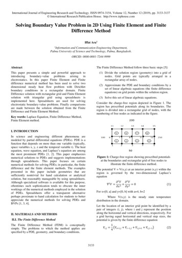
boundary conditions by Galerkin finite element method yet. So in this paper, our main concern is to solve the nonlinear boundary value problems with all boundary conditions by using Galerkin finite element method. 2. Finite Element Formulation for Second Order Linear BVPs Let us consider the general second
nite element method for elliptic boundary value problems in the displacement formulation, and refer the readers to The p-version of the Finite Element Method and Mixed Finite Element Methods for the theory of the p-version of the nite element method and the theory of mixed nite element methods. This chapter is organized as follows.
Nonlinear Finite Element Method Lecture Schedule 1. 10/ 4 Finite element analysis in boundary value problems and the differential equations 2. 10/18 Finite element analysis in linear elastic body 3. 10/25 Isoparametric solid element (program) 4. 11/ 1 Numerical solution and boundary condition processing for system of linear
the boundary). The boundary layer theory was invented by Prandtl back in 1904 (when the rst bound-ary layer equation was ever found). Prandtl assumes that the velocity in the boundary layer depends on t, xand on a rescaled variable Z z where is the size of the boundary layer. We therefore make the following Ansatz, within the boundary layer,
License Renewal Boundary Diagram Index By Boundary No. [To determine drawing number, delete "L" designator from Boundary Diagram Number] Boundary Boundary Vol. Number Diagram No. Title No. Buildings EL-10173 General Building Site Plan 1 1A70-B01 HL-16062 Nuclear Boiler System P&ID Sh.1 3 1 B11-B01 HL-16066 Reactor Recirculation System P&ID 3 .
A triple reciprocity boundary element method is discussed for analyzing heat conduction problems. This method is similar to the well-known dual reciprocity method in that the domain integral in the boundary integral equation is eliminated by approx
1 Overview of Finite Element Method 3 1.1 Basic Concept 3 1.2 Historical Background 3 1.3 General Applicability of the Method 7 1.4 Engineering Applications of the Finite Element Method 10 1.5 General Description of the Finite Element Method 10 1.6 Comparison of Finite Element Method with Other Methods of Analysis
boundary elements, however, is that di erent to the nite domain methods as, e.g., the nite di erence method or the nite element method, the methodology of formulating boundary value problems as boundary integral equations describes problems only by equa-tions with known and unknown boundary states.Hence, it only requires discretization ofFile Size: 847KB
‣ Problem formulation: PDE vs. boundary and volume integral equations ‣ Boundary integral equation method: Collocation, Galerkin Boundary Element Method (BEM) and Nyström methods for boundary integral equations,
Keywords: Boundary element methods, generalized inverse matrices, variational methods. 1 Introduction The resultant equations of the conventional boundary element method (CBEM) cannot be derived through variational considerations. Any e
boundary conditions following the standard finite element procedure. In addition the enrichment functions are easily obtained. 2. GENERALIZED FINITE ELEMENT METHOD The Generalized Finite Element Method (GFEM) is a Galerkin method whose main goal is the construction of a fin
The Finite Element Method [3], which I will present in this thesis, is a widely used numerical technique for obtaining rigorous solutions to boundary-value problems. 1.1.2 Introduction to Finite Element Method Starting from aircraft structure, the Finite Element Method (FEM) has been widely
Generalized coordiDate finite element lDodels ·11 17 'c. IT,I .f: 20 IS a) compatible element mesh; 2 constant stress a 1000 N/cm in each element. YY b) incompatible element mesh; node 17 belongs to element 4, nodes 19 and 20 belong to element 5, and node 18 belongs to element 6. F
bliss element glass tile anatolia tile stone anatoliatile.com bliss - element glass tile 01 3" x 9" element ice beveled glass tile 38-018 3" x 12" element ice glass tile 38-000 3" x 12" element ice artisan glass tile 38-010 1.5" x 6" element ice stacked glass mosaics 35-114 element ice chevron glass mosaics 35-122
Boundary Element Method. The generalized winding number def-inition is equivalent to solving the Laplace equation ( u 0) using the boundary element method with jump boundary conditions (i.e., mesh with boundaries ray stabbing fast winding number Fig. 4. A
the Source 1 power source until the Source 2 power source does appear. Conversely, if connected to the Source 2 power source and the Source 2 power source fails while the Source 1 power source is still unavailable, the ATS remains connected to the Source 2 power source. ATSs automatically perform the transfer function and include three basic .
Finite element method is used by implementing in MATLAB using a four node quadrilateral element. Then, a set of results are presented to show the applicability of the present problem to various types of boundary . Vibration Analysis; Finite Element Methods; Isotropic Plate; Boundary condition, shape funct
such as boundary integral equation method [5,6], finite element method [7,8], boundary perturbation method [9]. Recently, the scattering problems for elastic waves have received much attention due to the important applications in seismology and geophysics [10–12]. This paper concerns the scattering of a time-harmonic elastic plane wave by
Finite element mesh and boundary conditions 9. The finite element mesh and the displace-ment boundary conditions are shown in Fig. 3. '-The idealized geometry (see Fig. 1) is symmetri- I cal about the centre line, so the mesh represents one-half of the cross-section through the tunnel. ;', The lower horizontal boundary to the mesh was
What are boundary integral equations? We can reformulate boundary value problems for PDEs in a domain as integral equations on the boundary of that domain. We typically use them for linear, elliptic, and homogeneous PDEs, but not always. Boundary integral equation methods refer to the numeric
For turbulent flow: The thermal boundary layer thickness for turbulent flow does not depend on the Prandtl number but instead on the Reynolds number. T V T _ 0.37t uv † ‡ 0.37tuv † db This turbulent boundary layer thickness formula assumes: (1) The flow is turbulent right from the start of the boundary layer.
Boundary Scan IC. The Boundary Scan cells are integrated between core logic and physical contact pins. They enable the test of connections between the pins of ICs, even those without Boundary Scan cells. JTAG / Boundary Scan is very versatile and can be utilised in the entire production process, e.g. for emulation, design
The boundary element method (BEM) has o ered an alternative to the nite element method and has been attractive for certain types of problems, such as those involving an in nite or semi-ini nite domain [5]. The isogeometric approach [7] has led to rene
The boundary element method (BEM) belongs to the first category; but it is advantageous over the finite element method (FEM) for a number of reasons. In the BEM approach, discretization takes place only on the surface rather than throughout the entire volume, with
Open source software Open source software has been a nebulous reference to any software that is free, and is often confused with freeware and shareware. The Open Source Initiative (OSI; www. opensource.org) has therefore become a certification body for open source software under a commonly agreed-upon definition for "open source".
open source: boundless suite 4.9.1 4 open source: geonode 2.8 5 open source: deegree3 3.3.2 (osgeo-live dvd 11.0) 5 open source: geomajas 2.4.0 (osgeo-live dvd 11.0) 5 installation of open source web gis applications 6 visual model: web gis application features grouped by functionality 6 functionality comparison matrix 7 summary 9
dimensional (2D) and three-dimensional (3D) elastostatic problems in the framework of the Form-II strain-gradient theory of Mindlin. Although the proposed boundary element methodology concerns boundary value problems with smooth and non-smooth boundaries, the numerical examples presented here are confined to smooth boundaries. The BEM solution of
This includes the space{time nite element formulations, immersed boundary methods, level-set method, ctitious domain method, un- tted nite elements, and arbitrary Lagrangian{Eulerian (ALE) formulation, see, e.g., [9{17]. In this paper we propose a nite element method based on a quasi-Lagrangian formulation of the equations in the reference domain.
CHEMISTRY — RELEASED ITEMS 6 Go to the next page. 15 The table below shows the electron configurations of three elements. Element Electron Configuration Element 1 1s22s22p2 Element 2 1s22s22p5 Element 3 1s22s22p4 What is the order of the elements from smallest to largest atomic radius? A Element 1, Element 2, Element 3
Description This is a Matlab /Octave/Freemat/Scilab code for testing the gls.m routine for solving the linear system . Licence This is 'open source'; the software may be used and applied within other systems as long as its provenance is appropriately acknowledged. See the GNU Licence for more information or contact webmaster@boundary .
The Finite Element Method The Finite Element Method (FEM) is a numerical technique for solving PDEs. FEM was originally applied to problems in structural mechanics. Unlike FDM, FEM is better suited for solution regions having irregularly shaped boundaries. The finite element analysis involves four basic steps [4, 5]:
3.4 Multi-element assemblies 62 3.5 "Element-by-element" or "Mesh-free" techniques 64 3.5.1 Conjugate gradient method 64 3.5.2 Preconditioning 65 3.5.3 Unsymmetric systems 66 3.5.4 Symmetric non-positive definite equations 67 3.5.5 Symmetric eigenvalue systems 67 3.6 Incorporation of boundary conditions 68 3.7 Programming using building blocks 70
Base: 159 director decision makers for open source adoption and/or cloud strategy in North America. Source: A commissioned study conducted by Forrester Consulting on behalf of Perforce, March 2021. Optimized approach Supporting open source Onboarding open source Migrating existing tools/workloads to open source Comprehensive capabilities
Open Source Used In Open Source Documentation Used in SD-WAN 3.5 2 This document contains licenses and notices for open source software used in this product. With respect to the free/open source software listed in this document, if you have any questions or wish to receive a copy of any source code to which you may be entitled under
The finite element method (FEM), or finite element analysis (FEA), is a computational technique used to obtain approximate solutions of boundary value problems in engineering. Boundary value problems are also called field problems. The field is the domain of interest and most often represents a physical structure.
1.2. FINITE ELEMENT METHOD 5 1.2 Finite Element Method As mentioned earlier, the finite element method is a very versatile numerical technique and is a general purpose tool to solve any type of physical problems. It can be used to solve both field problems (governed by differential equations) and non-field problems.
11 The Finite Element method Lab Objective: The nite element method is ommonlyc used for numerically solving artialp di erential quations.e We intrducoe the nite element method via a simple BVP describing the steady state distribution of heat in a pipe as uid ows through. Advection-Diffusion of Heat in a Fluid We begin with the heat equation y .


