Device Circuit Co Design Analog Mixed Signal Hf Hs Design-PDF Free Download
Introduction What is Analog Design? Skillset for Analog IC Circuit Design Trends in Analog IC Design Notation, Terminology and Symbols Summary CMOS Analog Circuit Design, 3rd Edition Reference Pages 1-16 . Lecture 01 – Introduction (7/6/15) Page 01-2
EECE488: Analog CMOS Integrated Circuit Design Set 7 Opamp Design SM 1 EECE488 Set 7 - Opamp Design References: “Analog Integrated Circuit Design” by D. Johns and K. Martin and “Design of Analog CMOS Integrated Circuits” by B. Razavi All figures in this set of
No general analog design methodology. No general design approach . CAD tools for simulation, layout generation and post layout verification. Large number of analog design automation tools, but only in the university domain! Few analog design automation tools in industry. STATE OF THE ART Structured Analog CMOS Design, D. Stefanovic 1
2. ANALOG IC DESIGN: OVERVIEW In order to locate analog IC sizing, a brief presentation of a typical analog IC design flow is shown, and the analog IC sizing task is described. 2.1 Design Flow A commonly well accepted design flow for analog and mixed-signal ICs is depicted in Figure 1. It was proposed by Gielen and
Analog I/O 1 / 10 V or 0-10 V or 0-20 mA TIDA-01633 Analog I/O 2 / 10 V or 0-10 V or 0-20 mA Load fault feedback Current/Voltage output select Analog I/O select Analog input Analog input ref PWM Input Analog DAC x2 x2 x2 x2 x
analog signal Many electronic systems, particularly those dealing with low signal amplitudes or very high frequency required analog approach Lots of most challenging design problems are analog Good analog circuit designers are scarce (very well
Design-time Syndrome: In 10%–90% analog–digital die, 10% analog demands 90% of total design time. Pass(attempts)-to-Success Ratio: Digital Designs 1 and Analog Designs 2 – 3 Analog design cannot be automated, so there are no standard cell libraries. E.g.: Ope
23 January 2016 1. Dr. S. L. Pinjare School Of ECE, REVA University. Introduction to Analog Layout Design. 23 January 2016 2. Implementation of analog circuits and systems using integrated circuit technology. Unique Features of Analog IC Design. – Customized design – Designed at the circuit level. – Geometry is an important part of the design.
the right partition of signal processing between the analog and digital domain must be used. This is made possible by data converters converting data between the do-mains. A device converting an analog signal into a digital representation is called an analog-to-digital converter (ADC) and a device converting digital data into an analog
analog CMOS circuit design." We'll also introduce circuit simulation using SPICE (simulation program with integrated circuit emphasis). The introduction will be used to review basic circuit analysis and to provide a quick reference for SPICE syntax. 1.1 The CMOS IC Design Process The CMOS circuit design process consists of defining circuit .
The Cadence Design System includes several software packages for integrated circuit design, such as, schematic composer, circuit simulators, layout editor, and layout extraction and verification tools. Cadence design framework manages the process for development of analog, digital, and mixed-signal (with both analog and digital) integrated .
Analog Circuit Design is an essential reference source for analog circuit design-ers and researchers wishing to keep abreast with the latest development in the field. The tutorial coverage also makes it suitable for use in an advanced design. Contents Part I Low-Voltage Low-Power Data Converters
Before presenting state of the art approaches in analog layout generation, a brief introduction on analog design flow is provided. 2.1 Analog Design Flow Different analog design flows are available in literature, however the majority of the works developed in the last decade follow the design flow introduced by Gielen and Rutenbar [9].
Introduction to Analog Verification Analog Verification 2 of 13 Designer’s Guide Consulting www.designers-guide.com 1 Analog Verification Currently, 90% of all SOCs contain analog circuitry, and the analog con‐ tent of these SOCs averages a relatively constant 20% of the area of the SOC.
modulation equipment Analog data, digital signal – Permits use of modern digital transmission and switching equipme nt Digital data, analog signal – Some transmission media will only propagate analog signals – E.g., unguided media (air) Analog data, analog signal – Analog data in
Modulation of Analog Data 2 Why Analog-to-Analog Modulation? – two principal reasons for combining an an analog signal with a carrier at freq. f c: (1) higher freq. may be needed for effective transmission in wireless domain, it is virtually impossible to transmit baseband signals – the requi
Getting analog inputs to digital form D/A conversion “digital to analog” Getting digital inputs to analog form Digital I/O Sometimes you can fake analog values with digital (e.g., digital pulsing) 8 D/A Conversion “DAC” “D/A Converter” “Digital To Analog Converter
More specifically, the learning outcomes about CMOS analog circuit design are: 1. Create a typical full custom design flow for an analog circuit with an industrial CAD tool, as shown in Figure 1 2. Propose a detailed specification of an electronic circuit, including a functional block-diagram, a list of
Closing the Analog Design Loop with the Berkeley Analog Generator by Nicholas Werblun Master of Science in Electrical Engineering and Computer Sciences University of California, Berkeley Professor Vladimir Stojanovi c, Chair Analog and mixed signal IC design is noto
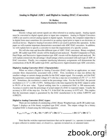
Figure 6. Three-bit, Flash Type Analog to Digital Converter Circuit Analog to Digital Converter (ADC): When selecting an Analog to Digital converter (ADC) chip for an application, three characteristics must be considered. Similar t
circuit protection component which cars he a fusible link, a fuse, or a circuit breaker. Then the circuit goes to the circuit controller which can be a switch or a relay. From the circuit controller the circuit goes into the circuit load. The circuit load can be one light or many lights in parallel, an electric motor or a solenoid.
Series Circuit A series circuit is a closed circuit in which the current follows one path, as opposed to a parallel circuit where the circuit is divided into two or more paths. In a series circuit, the current through each load is the same and the total voltage across the circuit is the sum of the voltages across each load. NOTE: TinkerCAD has an Autosave system.
Chaoli Ang Team#3 Application Note Analog Circuit Design and Simulation with TINA-TI 2 Introduction TINATM is a Spice-based circuit simulation tool suitable for running in Microsoft Windows Operation system. TINATM is able to precisely simulate analog
The lecture “Analog Integrated Circuit Design” aims at teaching the basic principles, basic circuit blocks and the basic working methods that an analog designer needs to know. Nowadays, microchips have a high amount o
What is a Digital Analog Converter? Introduction In electronics, a digital-to-analog converter (DAC or D-to-A) is a device for converting a digital (usually binary) code to an analog signal (current, voltage or electric charge). An analog-to-digital converter (ADC) performs the
videos, a summary of dedicated analog development tools and a link to download the powerful MPLAB Mindi Analog Simulator in this Analog Design eBook. Discover the full range of advanced analog products with the interactive Treelink selector and explore the detailed documentation whic
DIR-330 A1 Device 6-18-2016 DIR-130 A1 Device 6-18-2016. DFE-690TXD A4 Device 6-8-2016 DFE-538TX F2 Device 6-8-2016 DFE-528TX E2 Device 6-8-2016 DXS-3250E A1 Device 5-31-2016 DXS-3250 A1 Device 5-31-2016 DXS-3227P A1 Device 5-31-2016 DXS-3227 A1 Device 5-31-2016 DEM-411T A1 Device 5-31-2016
4. Design of Discrete-Time IIR Filters from Continuous-Time Filters Motivation for Digital Filter from Analog Filter Analog IIR filter design is highly advanced. Have relatively simple closed form design The methods do not lead to a simple closed form design formulas for discrete-time IIR case. Analog Filters An analog filter may be described as
Complexity in Analog Design Analog design is normally done in a non-hierarchical manner and makes little use of repeated blocks. As a consequence, analog design can become quite complex and challenging. How do you handle the complexity? 1.) Use as much hierarchy as possible. 2.) Use appropriate organization techniques. 3.) Document the design .
aesthetic concerns, which are crucial principles in analog layout [4, 8]. The aesthetic in analog routing is a relief for correctness to describe hard-to-model relations in analog layout and design expertise. Existing analog routing algorithms are still limited to consider such sophisticated scenarios.
1.1.2. Tradeoffs in analog design Analog circuits present a large variety of circuit functions, performance objectives, and specification methodologies [2]. The basic elements of modern analog circuits are MOS transistors, which are highly non-linear devices. Even a simple cell a
Simulation with Affirma Analog Circuit Design Environment (parametric analysis) . (IC445) for a typical bottom-up digital circuit design flow with the AMI06 process technology and NCSU design kit. Tutorial A, covers setup of the Cadence environment on a UNIX platform, use of the Virtuoso schematic entry tool, and use of the Affirma analog .
Analog Circuit Design Objective: Translate circuit specifications (gain, bandwidth, dynamic range, ) into transistor sizes and bias currents Challenge: Accurate device models for deep submicron transistors – “Square-law model” – Simulation models (B
circuit design will be addressed such as the increased leakage and variability with scaling technologies. Next, the impact of this on digital circuit design and embedded memories is discussed. Finally, problemsbothering embedded analog circuits are presented, such as reducing supply voltages,poor design productivity and signal
An analog-to-digital converter (abbreviated ADC, A/D or A to D) is a device which converts continuous signals to discrete digital numbers. The reverse operation is performed by a digital-to-analog converter (DAC). Typically, an ADC is an electronic device that converts an input analog voltage (or current) to
analog design automation tools, the technology trend toward integrating complete systems on a chip in recent years has provided yet another driving force to bolster analog CAD efforts. In addition, for such systems new design paradigms are being developed that greatly affect how we will design analog blocks.
Analog-to-Digital Converter (ADC) The TMS320x2833x ADC module is a 12-bit pipelined analog-to-digital converter (ADC). The analog circuits of this converter, referred to as the core in this document, include the front-end analog multiplexers (MUXs), sample-and-hold (S/H) circuits,
Converter (ADC) and Digital-to-Analog Converter (DAC). 1.2.2. Analog-to-Digital Converter (ADC) The transducer’s electrical analog output serves as the analog input to the ADC. The ADC converts this analog input to a digital output. This digital output consists of a number of bits that
Lesson 20: Analog to Digital Conversion Objectives: (a) Describe the advantages of digital over analog communication. (b) Discuss the basic steps of the analog-to-digital conversion process: sampling, and quantizing/encoding. (c) Given an analog waveform, sampling rate, and resolution
Cisco ATA 191 Multiplatform Analog Telephone Adapter The Cisco ATA 191 Multiplatform Analog Telephone Adapter is a 2-port handset-to-Ethernet adapter that brings traditional analog devices into the IP world. Product Overview The Cisco ATA 191 Multiplatform Analog Telephone Adapter turns traditional telephone, fax, and overhead paging


