Digital Modulation In Communications Systems An Introduction-PDF Free Download
9/18/2016 9Nurul/DEE 3413/Modulation Types of Modulation Pulse Modulation Carrier is a train of pulses Example: Pulse Amplitude Modulation (PAM), Pulse width modulation (PWM) , Pulse Position Modulation (PPM) Digital Modulation Modulating signal is analog Example: Pulse Code Modulation (PCM), Delta Modulation (DM), Adaptive Delta Modulation (ADM), Differential Pulse
Types of Modulation 6 Flynn/Katz 7/8/10 Analog Modulation Amplitude Modulation, AM Frequency Modulation, FM Double and Single Sideband, DSB and SSB Digital Modulation Phase Shift Keying: BPSK, QPSK, MSK Frequency Shift Keying, FSK Quad
10.3 Analog Modulation Schemes 10.4 Amplitude Modulation 10.5 Frequency Modulation 10.6 Phase Shift Modulation 10.7 Amplitude Modulation And Shannon's Theorem 10.8 Modulation, Digital Input, And Shift Keying 10.9 Modem Hardware For Modulation And Demodulation 10.10 Optical And Radio Frequency Modems 10.11 .
Modulation allows for the designated frequency bands (with the carrier frequency at the center of the band) to be utilized for communication and allows for signal multiplexing. Amplitude modulation (AM) is an analog and linear modulation process as opposed to frequency modulation (FM) and phase modulation (PM).
modulation & demodulation modulation & demodulation Fig.7 shows the experimental setup of realization of both modulation and demodulation of AM and FM . Chapter 5, Traditional Analog Modulation Techniques, Mikael Olofsson, 2002-2007. [4] K.Sharma, A.Mishra & Rajiv Saxena, „Analog & Digital Modulation Techniques: An overview .
3. Amplitude Modulation . a. General. The amplitude, phase, or frequency of a carrier can be varied in accordance with the intelligence to be transmitted. The process of varying one of these characteristics is called modulation. The three types of modulation, then are amplitude modulation, phase modulation
4.1. ANGLE MODULATION 11 1 1 11 1 1 tt /3 phase step at t 0 3 Hz frequency step at 0 Phase Modulation Frequency Modulation f c f c f f 3 Hz Phase and frequency step modulation 4.1.1 Narrowband Angle Modulation Begin by writing an angle modulated signal in complex form x c.t/DRe A ce j!ctej .t/ Expand ej .t/in a power series x c.t/DRe A .
Ans: Modulation is defined as the process in which some characteristics of the signal called carrier is varied according to the modulating or baseband signal. For example – Amplitude Modulation, Phase Modulation, Frequency Modulation. In case of over modulation, the modulation index is
Second Edition. Simon Haykin, Michael Moher. Chapter 5 Pulse Modulation : Transition from Analog to Digital Commu nications. 5.1 Sampling Process 5.2 Pulse-Amplitude Modulation 5.3 Pulse-Position Modulation 5.4 Completing the Transition from Analog and Digital 5.5 Quantization Process 5.6 Pulse-Code Modulation 5.7 Delta Modulation 5.8 Differential .
Oct 29, 2014 · Reasons for Analog Modulation ! Modulation of digital signals " When only analog transmission facilities are available, digital to analog conversion required ! Modulation of analog signals " A higher frequency may be needed for effective transmission " Modulation permits frequency division multi
Fundamentals of Satellite Communications Part 3 Modulation Techniques used in Satellite Communication 1. Early Communication 2. Simultaneously Transmitting Multiple Signals 3. Types of Modulation 4. Digital Modulation -Quantizing Data 5. Digital Modulation Techniques –CW (Constant
Department of Electronics & Communication Engineering Page 3 1.Amplitude Modulation & Demodulation Aim To study the function of Amplitude Modulation & Demodulation (Under modulation, Perfect modulation & Over modulation) using Matlab Simulink. Apparatus Required
– Analog modulation is also called continuous-wave (CW) modulation. – AM radio, FM radio, first generation cell phone system Digital modulation – m(t) is a digital signal Take finite number of values E.g. {-1, 1}, {-2, -1, 1, 2}, – 2nd generation cell phone system – Digital modulati
Analog Linear Modulation and Demodulation Goal: The goal of this experiment is to study and analyze the analog linear modulation and demodulation techniques in communication systems. Theory: Analog linear modulation In electronics and telecommunications, modulation is th
i-Single pulse width modulation. ii-Multiple pulse width modulation. iii-Sinusoidal pulse width modulation. iv-Modified Sinusoidal pulse width modulation. v-Phase- displacement control. vi-Space vector pulse width modulation. In a speed control systems, with a wide range of generated f
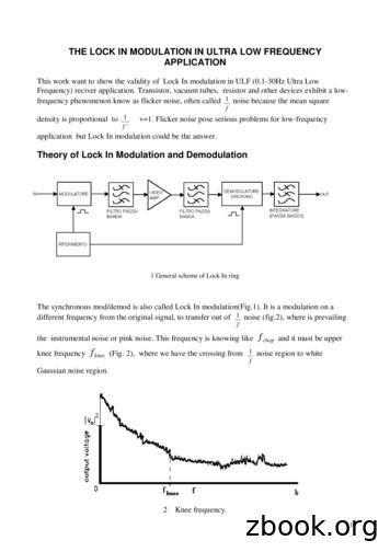
application but Lock In modulation could be the answer. Theory of Lock In Modulation and Demodulation 1 General scheme of Lock In ring The synchronous mod/demod is also called Lock In modulation(Fig.1). It is a modulation on a different frequency from the original signal, to transfer out of f 1 noise (fig.2), where is prevailing
Introduction to Analog Modulation Analysis Edward Pan edward.pan@rigol.com Rev.1.0 2017-OCT. RIGOL TECHNOLOGIES, INC. Basic Concept AM/FM Modulation AM/FM modulation technology is one kind of traditional analog modulation in Radio communication system. It uses variable amplitude carieer to modulate the original signal. Like the voice or Audio .
modulation and multiplexing techniques in Section 3 to be used to extend the single-bit embedding to multiple-bit embedding. We shall cover amplitude modulo modulation, orthogonal/bi-orthogonal modulation, and TDMA/ CDMA type modulation/multiplexing. These techniques are quantitatively compared in Section 4.
Modulation for multiplexing –This allows for multiple signals to be carried on a single transmission medium (multiplexing is one form of modulation). Modulation to overcome equipment limitations –Modulation is used to place signals in a portion of the spectrum where equipment limitations are minimal or most easily met.
R&S FPL1000 into an analog modulation analyzer for amplitude-, frequency- or phase-modulated signals. It measures not only characteristics of the useful modulation, but also factors such as residual FM or synchronous modulation. The R&S FPL1 Analog Modulation Analysis application features: AM, FM, a
FM Modulation and Demodulation Goal: The goal of this experiment is to become familiar with FM modulation and demodulation. Theory and background: 1. FM modulation: Frequency modulation (FM) is a process in which the carrier frequency is varied by the amplitude of the modulating signal (i.e.,
2,1 The Principles of Delta and Delta-Sigma Modulation. 2.2 Early work by de Jager on Delta Modulation. 2.3 A Review of Zetterbergis paper "A Comparison. Between Delta and Pulse Code Modulation". 2.4 Delta-Sigma Modulation. 2.5 Thermal Noise Considerations. 2.6 The Problem of Obtaining Output Spectrum of a Delta Modulator in Terms of the Input .
2.2.2. Settings in the Modulation Panel Modulation Type ASK, either 100% or 10%. This modulation is not available as standard, but a user defined modulation can be used. Please refer to the annex (Chapter 8) for instructions on how to create user modulation files. The files for 100% ASK ans 10% ASK are supplied with this application note.
Chapter 3: Digital Modulation Schemes Po-Ning Chen, Professor Institute of Communications Engineering National Chiao-Tung University, Taiwan Digital Communications: Chapter 3 Ver. 2018:07:12 Po-Ning Chen 1 / 161. 3.1 Representation of digitally modulated signals
recognition of signal modulation patterns is the research content of this article. Only by thoroughly understanding the modulation principles of different types of communication signals and finding the essential differences between various types of signals can a modulation recognition algorithm with higher performance be designed.
2.5 Digital Modulation and Multiplexing. Digital modulation transferring a digital bit stream over an analog, bandwidth-limited communication channel, for example over A voice channel on the public switched telephone network (frequency range 300-3400 Hz) A limited radio frequency band (e.g. the 902-929 MHz ISM band)
Chapter 3: Digital Modulation Schemes Po-Ning Chen, Professor Institute of Communications Engineering National Chiao-Tung University, Taiwan Digital Commu
modulation schemes have greater capacity to convey large amounts of information than analog modulation schemes. 1.1 Trading off simplicity and bandwidth There is a fundamental tradeoff in communication systems. Simple hardwa
and [11]. These texts provide comprehensive coverage of communications systems; mostly presenting analog and then digital modulation. An ebook will be presented which follows a different way to teach communications systems; an approach that uses a student driven interactive presentation of the fundamentals of communications systems .
VCO modulation input, and the other to the PLL master oscillator. Since the master oscillator is not in the frequency control feedback loop, it can be modulated by the low-frequency portion of the signal. Modulation at this point, combined with modulation of the VCO, produces a composite signal with a spectral response extending down to DC.
AN4990 Sigma-delta modulation principle (external analog front-end functioning, simulations) 55 2 Sigma-delta modulation principle (external analog front-end functioning, simulations) 2.1 Principle of sigma-delta modulation The basic functional block diagram of a sigma-delta modulator is presented on Figure 4. Figure 4. Sigma-delta modulation .
The modulation and multiplexing techniques that were used at this time were analog, adapted from the technology developed for microwave links in the previous two decades. Frequency Modulation (FM) was the modulation of choice and Frequency Division Multiplexing (FDM) was used to combine hundreds or thousands
Analyze a wide range of standards, modulation formats, and line coding RFID standards vary widely and use many modulation formats and line coding. Option 89601BHTC is flexible enough to handle multiple standards, including EPCGen2, NFC formats 14443 Type A or B, and ISO 15693. Choose setup presets and adjust required parameters.
DRI-STEEM Vapor-logic3 *OTUBMMBUJPO BOE 0QFSBUJPO .BOVBM t 1BHF 51 NPEVMBUJPO TP modulation (electric humidifiers) The standard form of modulation with an electric humidifier is time proportioning (TP) modulation. With TP modulation, the outputs cycle on and off at a certain rate to approximate humidifier demand as the example below illustrates.
142 - D1 Adaptive delta modulation ADAPTIVE DELTA MODULATION ACHIEVEMENTS: introduction to a variation of the basic delta modulator, which adjusts the step size according to the slope of the signal being sampled PREREQUISITES: completion of the experiments entitled Delta modulation and Delta demodu
Vestigial Sideband Modulation (VSB) Some observations SSB modulation is well suited for transmission of voice signals (or for all signals which exhibit a lower component at f 0). DSB generation is much simpler, but requires twice the signal bandwidth. VSB modulation represents a compromise
OTFS modulation, when implemented using pre- and post-processing to existing multicarrier modulation schemes, can be viewed as a series of transformations at the transmitter and receiver. The block diagram of the OTFS modulation scheme is shown in Fig. 2, where the inner box is the familiar multicarrier (TF)
Pulse-width modulation (PWM), or pulse-duration modulation (PDM), is a commonly used technique for controlling power to inertial electri-cal devices, made practical by modern electronic power switches. Here we apply PWM techniques like Sinusoidal pulse width modulation (SPWM)
Sinusoidal pulse width modulation (Carrier based Pulse Width Modulation Technique), Space vector pulse width modulation Single pulse modulation contains only one pulse per half cycle and the width of the pulse can be used to control the output voltage. In mul
modulation, Multiple pulse modulation and Sinusoidal pulse width modulation (Carrier based Pulse Width Modulation Technique). SVPWM technique is explained in detail which improves the quality of the current and reduce the torque ripple in induction motor drive while maintai


