Thrust Restraint PAAWWA 4 15
DIPRA Member Companies1915DIPRA Website(www.dipra.org)DIPRA Computer ProgramsThickness Design of Ductile Iron PIpeHydraulic Analysis of Ductile Iron PipeThrust Restraint Design for Ductile Iron PIpeDesign of Ductile Iron Pipe on SupportsAWWA StandardsANSI/AWWA C104/A21.4 Cement-Mortar LiningsANSI/AWWA C105/A21.5 Polyethylene EncasementANSI/AWWA C110/A21.10 Ductile-Iron and Gray-Iron FittingsANSI/AWWA C111/A21.11 Rubber-Gasket JointsANSI/AWWA C115/A21.15 Flanged Ductile-Iron PipeANSI/AWWA C116/A21.16 Fusion-Bonded Epoxy Coatings for FittingsRestrainingThrust ForcesANSI/AWWA C150/A21.50 Thickness DesignANSI/AWWA C151/A21.51 Ductile-Iron Pipe, Centrifugally CastANSI/AWWA C153/A21.53 Ductile-Iron Compact FittingsANSI/AWWA C600 Installation of Ductile-Iron Water MainsAWWA Manual M41 Ductile-Iron Pipe and Fittings1
Forces Causing ThrustThrust ForceStraight RunStatic forces(Internal pressure)Dynamic forcesPAPA(Fluid velocity)Thrust ForceBend 2PA Sin( /2)Resultant Thrust: 90 BendPressure at 150 psiNominalPipe 44,39648429,95664718,506Restraining TechniquesThrust blocksRestrained joint systemTie rodsCombined systems2
Types of Thrust BlocksBearing Thrust BlockUndisturbed SoilBearing Area45 45 BearingGravityBearing Area (ft2) Soil Bearing Strength SBSoilSB (lb/ft2)Muck0Soft clay1,000Silt1,500Sandy silt3,000Sand4,000Sandy clay6,000Hard clay9,000Safety Factor Thrust Force (lbs)Bearing Capacity of Undisturbed Soil (lbs/ft2)Bearing Thrust BlockHtTA hb hT(S )SB fh 1/2HtBearing Block ConstructionRight45 TWrong45 T3
Thrust RestraintGravity Thrust BlockGravity BlockGravity Block Size (ft3) Safety Factor Thrust Force (lb)Density of Block Material (lb/ft3)Restrained Joint Force SystemL PA Tan( /2)Ff ½ RsPALPA Sin( /2) FfRs[Ff ½ Rs]LCos( /2)4
Restrained JointsMechanical Joint Retainer GlandsSet-ScrewMechanical JointRetainer GlandWedge-actionMechanical JointRetainer GlandRestrained Joints5
Designing Thrust SystemsRestrained Joint Force SystemL Thrust Restraint BrochurePA Tan( /2)Ff ½ RsPALA brochure outlining design theoryand a design aid of restrainedjoint systems for ductile iron pipe.PA Sin( /2) Ff[Ff ½ Rs]LCos( /2)RsRestrained Length Dependant UponSuggested Values for Soil Propertiesand Reduction ConstantKnPipe sizeType of fittingSoilDesignationSoil Description (deg)f Cs(psf)fcγ(deg)2*345Clay 1Clay of medium to low plasticity,LL 50, 25% coarse particles[CL & CL-ML]00300.50.8090.20.40.60.85Coh-granCohesive granular soils, 50% coarse particles [GC & SC]20.40.65200 .4090.40.60.851.0Sand SiltSand or gravel w/silt, 50% coarse particles [GM & SM]30Good SandClean sand, 95% coarse particles,[SW & SP]36Internal pressureDepth of coverSoil characteristicsLaying conditions.50.75.75.80A21.50 nsult Table 3 of thrust brochure for pertinent notes.Laying ConditionsThrust Restraint - Research12” MJ Pipe and fittingswith DI retainer glandsType 1Type 2MovementsensingprobesType 3Measurement TrenchMeasuringFrameRailroad CrossTie BulkheadBackfilledProbeType 4Type 5Approximately3’ of coverBedding compactionvaried during testSection “A-A”6
Table B-5Designing Thrust SystemsA21.50 – Laying ConditionsSoil Type: Coh-granSoil Parameters 20 degreesCs 200 psf 90 pcfThrust Restraint Computer ProgramtiSize Depth(in)(ft)A computer program to aid inthe design of restrained jointsystems for ductile iron pipe.2RestrainedLength (ft)90 1.00045 0.41422½ 0.19911¼ .00A21.50 – Laying Conditions34RestrainedRestrainedLength (ft)Length (ft)5RestrainedLength (ft)302.597 (112)69 (79)56 (62)50 (55)3.091 (105)65 (74)52 (58)47 (51)304.081 (93)57 (65)46 (51)41 (45)306.066 (76)46 (52)37 (41)33 (36)308.056 (64)38 (44)31 (34)28 (30)3010.048 (56)33 (38)26 (30)24 (26)Vertical Down Bend /2Tan( /2)30.40fc30Horizontal Bend Multiplier 2f 2PA Sin( /2)FsLPA Tan( /2)L SfTeeFfFsExtend Restrained Joints at:PAbCasingsBridge crossingsLrAboveground applicationsLbLb SfPAb -1/2 RsLr(Ff )bPoor soil conditionsClosely located fittingsLb(Ff)b7
Combined Horizontal Bends2PA Sin( /2)Vertical Offset2PA Sin( /2)2PA Sin( /2)2PA Tan( /2)L2 SfRsRsL1FfLLKnownKnownLL1 SfFf-LFf-LL22PA Tan( /2)L12PA Tan( /2)L1 SfLFfL1-LFf 1/2RsFfRsFf 1/2Rs2PA Sin( /2)Combined Vertical Equal Angle OffsetsFfFfLL1L1LLL2PA Tan( /2)L1 Sf-LFf8
Thrust Restraint - ClosuresL2ClosureL2ClosureL1Thrust Restraint – Deflected JointsL1Horizontal Bend / Vertical Up BendPA Tan( /2)Second unrestrained jointbegin deflectL SfFf ½ RsPALPA Sin( /2) First unrestrained jointdo not deflectFfRs[Ff ½ Rs]LCos( /2)TieRods9
Calculating Number of Tie RodsF SAN Sf T(X or Y)FWhere:CombinedSystemsF Force Developed per Rod (lbs.)S Tensile Strength of Rod Material (psi)A Cross Sectional Area of Rod (in.2)N Number of Rods RequiredT(X or Y) Thrust Force Component (lbs.)Sf Safety Factor (usually 1.5)InstallationDUCTILE IRON PIPETHE RIGHT DECISION10
ANSI/AWWA C105/A21.5 Polyethylene Encasement ANSI/AWWA C110/A21.10 Ductile-Iron and Gray-Iron Fittings ANSI/AWWA C111/A21.11 Rubber-Gasket Joints ANSI/AWWA C115/A21.15 Flanged Ductile-Iron Pipe ANSI/AWWA C116/A21.16 Fusion-Bonded Epoxy Coatings for Fittings ANSI/AWWA C150/A21.50 Thickness Design ANSI/AWWA C151/A21.51 Ductile-Iron Pipe .
34/00 NA Child Restraint Anchorages and Child Restraint Anchor Fittings 34/01 NA Child Restraint Anchorages and Child Restraint Anchor Fittings 34/02 NA Child Restraint Anchorages and Child Restraint Anchor Fittings 34/03 1/11/19 Child Restraint Anchorages and Child Restraint Anchor Fittings X (if fitted) 35/00 01/07/88 Commercial Vehicle Brake
are used in a designed thrust restraint system. Romac recommends using “The Thrust Restraint Design for Ductile-Iron Pipe published by the Ductile-Iron Pipe Research Association (DIPRA) to calculate the required length of restraint at a change in direction. For more information,
Actuator Thrust Applications. Thrust (Multi-Turn Valves) For Gates, Globes, or Sluice Gates, the thrust can be calculated from the pressure and valve data. Thrust and Torque Ratings must be considered when sizing. Valve threaded stem must not exceed thrust base limitations. Don’t plan on using tubing brackets for thrust
Designing Thrust Systems Thrust Restraint Brochure A brochure outlining design theory and a design aid of restrained joint systems for ductile iron pipe. Restrained Joint Force System PA PA Tan( /2) Ff ½ Rs L L Ff Rs PA Sin( /2) [Ff ½ Rs]LCos( /2) Restrained Length Dependant Upon Pipe
Jan 11, 2011 · The standard MX actuator thrust base is the A1 and may be bolted directly to the actuator. The thrust base contains a bronze alloy thrust nut that may be machined to suit the valve stem. An A1E thrust nut can be provided and may be installed to reach shorter stems. A1 base Housing, torque/ thrust Pipe plug Wa
Thrust Ball Bearing with Outer Cover The structure of thrust ball bearing with outer cover is the same as that of single direction thrust ball bearing, but, there is an outer cover on the seat washer (or there are outer covers on the inner and outer diameters of a seat washer). The structure is as Fig.1 and Fig.2. Thrust ball
The rotational speed of the thrust disk was measured by a photoelectric sensor, Sensor 3. All of the test data was recorded in the software of eZ-TOMAS 8.0 when the thrust disk was set in motion by hand. 3. Simplified Model The force analyses of the thrust disk and tilting pads are pre-sented in Figure 3. The thrust disk was floated on an air .
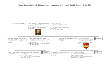
Marion Fanny Harris b: Coimbatore, India d: 26 July 1946 m: 4 November 1891 Eleanor Maud Gurney b: 1871 d: 1916 David Sutherland Michell b: 22 July 1865 Cohinoor, Madras, India d: 14 May 1957 Kamloops, British Columbia, Canada Charlotte Griffiths Hunter b: 1857 d: 1946 m: 6 August 1917 Winnipeg, Canada Dorothy Mary Michell b: 1892 Cont. p. 10 Humphrey George Berkeley Michell b: 1 October 1894 .


