AQT 56SE - Aquaemegsa
AQT-56SEELECTRONIC SERIESCON T RO L VA LVESPROGRAMMING MANUAL
TABLE OF CONTENTSGeneral Residential Installation3AQT-56SE Keypad4Control Operation5Master Programming - Setting the Time of Day6- Setting the Regeneration Mode7- Setting the Unit Capacity8- Setting the Regeneration Time & Hour Override10- Setting the Backwash Time11- Setting the Brine Time12- Setting Rapid Rinse Time13- Setting Brine Tank Fill Time14Product Features15AQT-56SE Dimensional Drawings183/4" Turbine Assembly & Parts List19Powerhead Assembly20Powerhead Assembly Parts List21Control Valve Assembly22Control Valve Assembly Parts List23Valve Wiring Diagram24Troubleshooting25Notes26CO N T R O L VA LV E SAQUATROL P.O. Box 2235 Chino Hills, CA 91709 USA
General ResidentialInstallationCO N T R O L VA LV E SWater PressureMinimum 25 PSIElectrical SupplyUninterrupted AC. Check voltage compatibilityExistingFree of any deposits or build-ups inside pipesSoftenerLocate close to drain and connect according to plumbing codesBypass ValvesAlways provide for bypass valve if unit is not equipped with oneCAUTIONDo not exceed 120 PSI water pressureDo not exceed 100 F water temperatureDo not subject unit to freezing conditionsGeneral Valve Installation ProcedureNote: Install the water softener with the inlet, outlet and drain connections made according to manufacturer’s recommendations and tomeet applicable plumbing codes.1. Locate the softener tank close to a drain where you wish to install the unit. Note: Be sure the tank is level and on a firm base.2. Perform all plumbing according to local plumbing codes. Use a 1/2" minimum pipe size for the drain. Use a 3/4" drain line for backwash flow rates that exceed 7 gpm or length that exceeds 20' (6 m).3. Cut the 1" distributor tube (1.050 O.D.) flush with top of each tank.Note: Only use silicone lubricant.4. Lubricate the distributor O-ring seal and tank O-ring seal. Screw the valve on to the tank.5. Use only Teflon tape on the drain fitting. Solder joints near the valve must be done before connecting any piping to the valve. Alwaysleave at least 6" (152 mm) between the valve and solder joints when soldering pipes that are connected to the valve. Failure to do thiscould cause damage to the valve.6. Be sure the floor under the brine tank is clean and level.7. Add water until there is approximately 1" (25 mm) of water above the grid plate. If a grid is not utilized, fill to the top of the air check inthe brine tank. Do not add salt to the brine tank at this time.8. On units with a bypass, place in Bypass position. Turn on the main water supply. Open a cold soft water tap nearby and let water run a few minutes or until the system is free of foreign material (usually solder)resulting from the installation. Close the water tap when water runs clean.9. Place the bypass in the In Service position and let water flow into the mineral tank. When water flow stops, slowly open a cold watertap nearby and let water run until air is purged from the unit. Then close tap.10. Plug the valve into an approved power sourcePage 3
AQT-56SEKeypadCO N T R O L VA LV E S11. Flow Meter Indicator211:305341000GAl2. Time of day3. Status4. Volume Remaining5. Regeneration mode- Timer- Meter Immediate- Meter DelaySettings Button1. Enter into setting menu2. Confirm the current setting, and enter into the next step3. When used simultaneously with up button, will enter into master programmingUp Button1. Adjust current settings (increase)2. Go to the last stepDown Button1.Adjust current setting (decrease)2.Go one step backCycle ButtonPage 41.Save the setting and return to service2.Enter into queued regeneration mode3.A long press for 5-6 seconds, initiate a immediate regenerate4.Terminate the current regeneration step and goes to the next step
CONTROL OPERATIONRegeneration ModesCO N T R O L VA LV E STime Clock Delayed ControlA Time Clock Delayed Control regenerates the system on a timed interval. The control willinitiate a regeneration cycle at the programmed regeneration time when the number of dayssince the last regeneration equals the regeneration day override value. The interval time can beprogrammed in a 24 hours base (1 day). Example, 24, 48, 72, 96, and so on. Or each 3, 4, 6, 8 or 12hours if your need is less than 24 hours.Meter Immediate ControlA meter immediate control measures water usage and regenerates the system as soon as thecalculated system capacity is depleted. The control calculates the system capacity by dividingthe unit capacity (typically expressed in grains/unit volume) by the feed water hardness andsubtracting the reserve. Meter Immediate systems generally do not use a reserve volume. AMeter Immediate control will also start a regeneration cycle at the programmed regenerationtime if a number of days equal to the regeneration day override pass before water usage depletesthe calculated system capacity.Meter Delayed ControlA Meter Delayed Control measures water usage and regenerates the system at the programmedregeneration time after the calculated system capacity is depleted. As with Meter Immediatesystems, the control calculates the system capacity by dividing the unit capacity by the feedwater hardness and subtracting the reserve. The reserve should be set to insure that thesystem delivers treated water between the time the system capacity is depleted and theactual regeneration time. A Meter Delayed control will also start a regeneration cycle at theprogrammed regeneration time if a number of days equal to the regeneration day override passbefore water usage depletes the calculated system capacity.Control Operation During RegenerationDuring regeneration, the control displays a special regeneration display. In this display, thecontrol shows the current regeneration step number the valve is advancing to, or has reached,and the time remaining in that step. The step that displays, flashes until the valve completesdriving to this regeneration step position. Once all regeneration steps are complete the valvereturns to service and resumes normal operation.Control Operation During ProgrammingThe control only enters the Program Mode with the valve in service. While in the Program Mode,the control continues to operate normally monitoring water usage and keeping all displays up todate. Control programming is stored in memory permanently, eliminating the need for batterybackup power.Page 5
Master ProgrammingSetting the Time of DayCO N T R O L VA LV E SFirst Step - Setting Time of DayPress Simultaneously11:30Default setting 12:00 (24 hours)Press Settings Button and Up Button simultaneously to enter intoPrograming ModeSET- 1TIMEFlashingSet the hourFlashingPress Up or Down buttons tochange hours.11:30Press the Settings Button to acceptand continue.Set the minutesFlashingPress Up or Down buttons tochange minutes.Press the Settings Button to acceptand continue.Page 611:30
Master ProgrammingSetting the Regeneration ModeCO N T R O L VA LV E SSecond Step - Setting the Regeneration Mode11:30SET- 2TYPEDefault setting is "Timer"FlashingChoose Between Time, Meter Immediate or Meter DelayedTimerThis mode willnot show watercapacity options.11:30TYPE-TFlashing11:30Press Up or Down buttons to changemodeMeter imm.TYPE-Press the Settings Button to acceptand continue.MFlashing11:30Meter DelayTYPE-TMFlashingPage 7
Master ProgrammingSetting the Water CapacityCO N T R O L VA LV E SThird Step - Setting the Unit Capacity (Not shown if Timer Mode was selected in 2nd Step)11:30SET-3 C-UDefault setting is 1000 galFlashingSet Unit Measurement - Gallons, Liters or Cubic MetersGallons11:300100048,Press Up or Down buttonsto Change Unit between:GALFlashingGAL: GallonL: LiterM3: Cubic Meter11:30Liters01000Press the SettingsButton to acceptand continue.LFlashing11:30Cubic Meters01000M3FlashingPage 8
Master ProgrammingSetting the Water Capacity Cont.CO N T R O L VA LV E S11:3001000GALFlashing11:3001000GALFlashingPress Up or Down buttonsto set water capacity.Press the Settings Button toaccept, cursor moves left andthe number 11:3001000GALFlashingPage 9
Master ProgrammingSetting the Regeneration Time & Hour OverrideCO N T R O L VA LV E SFourth Step - Regeneration Time and Hours Override11:30S E T - 4 T-HFlashingTimer ModeMeter Imm & Meter Delay ModesDefault: 2:00 a.m. – 072 hoursHours Override range:3, 4, 6, 8, 12 hours, then every 24 hours (24, 48, 76 960)Default: 2:00 a.m. – OFFHours Override range:Every 24 hours (24, 48, 76 960)Use UP and DOWNbuttons to adjust theRegeneration TimeUse UP and DOWNbuttons to adjust theRegeneration Time11:3002H-07 202FlashingPress SET to go toHours OverridePress SET to go toHours OverrideH-07 211:3002FlashingUse UP and DOWNbuttons to adjustHours OverrideUse UP and DOWNbuttons to adjustHours OverrideH-07 2Flashing11:3013H-06 0FlashingPage 3002H-024Flashing
Master ProgrammingSetting the Back Wash TimeCO N T R O L VA LV E SFifth Step - Setting the Back Wash Time11:30SET-5 -BWFlashingSet the TimeDefault setting is 01511:30015-BW-FlashingPress Up or Down buttonsto change Back Wash time(Minutes)Range: 0 - 999Press the Settings Buttonto accept and continueto next digit11:30015-BW-Flashing11:30015-BW-FlashingPage 11
Master ProgrammingSetting the Brine TimeCO N T R O L VA LV E SSixth Step - Setting the Brine Time11:30SET-6 -BDFlashingSet the TimeDefault setting is 06011:30060-BD-FlashingPress Up or Down buttonsto change Brine time(Minutes)Range: 0 - 999Press the Settings Buttonto accept and continueto next digit11:30060-BD-Flashing11:30060FlashingPage 12-BD-
Master ProgrammingSetting Rapid Rinse TimeCO N T R O L VA LV E SSeventh Step - Setting the Rapid Rinse Time11:30SET-7 -RRFlashingSet the TimeDefault setting is 01011:30010Press Up or Down buttonsto change the Rapid Rinsetime (Minutes)Range: 0 - 999Press the Settings Buttonto accept and continueto next lashingPage 13
Master ProgrammingSetting the Brine Tank Fill TimeCO N T R O L VA LV E SEights Step - Setting the Water Filling Time11:30SET-8 -BFFlashingSet the TimeDefault setting is 01211:30012-BF-FlashingPress Up or Down buttonsto change the Water FillingTime (Minutes)Range: 0 - 99911:30012Press the Settings Buttonto accept and continueto next digit-BF-Flashing11:30012FlashingDonePage 14-BF-
Product FeaturesFeatures & DisplaysCO N T R O L VA LV E S1) Display in ServiceTimed Regeneration ModeThe display will show the current time, remaining time to the nextset regeneration, and the days override.11:3002:18 01-DReg. remaining timeMeter Immediate Regeneration ModeThe display will show the current time and the remaining treatedwater to the next regeneration.Reg. override days11:3060M3Reg. remaining capacity11:3060M3Meter Delay Regeneration ModeThe display will show the current time and the remaining treatedwater alternatively. When the remaining treated water counts downto zero the display changes to the regeneration time set by the user.11:3002:18Reg. remaining time2) Backlight ScreenThe backlight on the screen will go off automatically after one minute if no buttons are pressed. To light it up again press any button onthe touch pad.Page 15
Product FeaturesFeatures & Displays Cont.CO N T R O L VA LV E S3) Memory during power failureAll program settings are stored in permanent memory. Current valve position, cycle step elapsed, time of day are stored during the powerfailure. Reset the current time is necessity when power up.If the valve stopped at a regeneration stage when power failure, the valve will return to prior position when power up. It takes 4 to 5minutes to reset to the position.11:30The display shows as:The system will show the status whenpower failure after find the position.RESET4) Restore factory settings1) Pull out the power2) Press the3) Release the11:30button and plug in the power simultaneouslybuttonRESETThe system is now restored5) Manual regenerationQueued RegenerationWhen the valve is in service position press thebutton to activate the queued regeneration.Queued Regeneration means the system will initiate a regeneration at the time set. If missed, it will initiate on the next day.The display shows the Queued Regenerationin TIMER ModeThe display shows the Queued Regenerationin Meter Delay Mode11:3011:30FlashingFlashing02 : 1 8----02:18----The display shows the Queued Regeneration in Meter Delay Mode.The system will initiate a regeneration - either the treated water remaining counts down to zero or the remaining time countsdown to zero, whichever is e 1611:30M302:18----
Product FeaturesFeatures & Displays Cont.CO N T R O L VA LV E S5) Manual regenerationImmediate RegenerationWhen the valve is in service position, press and hold thebutton for 5 seconds, an immediate regeneration will be initiated.Examples:"BW" Flashing (ready to "Backwash")11:30GOTOBWWhen the time counts down to zero or press thebutton11:30015BW"BD" Flashing (ready to "brine)11:30GOTOBDThe display shows as:Stop RegeneratingWhen regenerating, press thesimultaneously,then stop regenerating the display will return to the serviceposition.11:30GOTOSRPage 17
AQT-56SEDimensional DrawingsPage 18CO N T R O L VA LV E S
3/4" TurbineAssembly & Parts ListCO N T R O L VA LV E SItem No.QuantityPart No.Description1156013Flow Straightener2150022-8Meter Cable Assembly3401013O-ring411220EMeter Body Assembly5250044Adpater Clip6202105ScrewPage 19
PowerheadAssemblyPage 20CO N T R O L VA LV E S
PowerheadAssembly Parts ListCO N T R O L VA LV E SItem No.QuantityPart No.Description11A-15613Front Cover21A-S0001Housing Assembly31A-15616-1Idler Pointer41A-13312Spring Idler51A-13017Idler Gear61A-15617Drive Gear72A-14457Spring84A-13300Ball91A-15622-1Main Gear and Shaft101A-15650Motor Mounting Plate117A-13296Screw12 *1132A-11384Screw141A-15614Back Cover15 *116107021DC Monotrematous Socket171A-12037Washer181A-S1002Brine Cam Assembly191A-13547Strain Relief20115619Drive 2015Screw25107089Circuit Board261S1003Panel271A-56296Front LabelMotorTransformer* Extra OptionPage 21
Control ValveAssemblyCO N T R O L VA LV E SBackwash Filter Injector OptionPage 22
Control ValveAssembly Parts ListCO N T R O L VA LV E SItem No.1234567891011121314151617 *1820212223 *2425 *26272829303132333435 *36 1422211111111111111121111112111111111111Part crewScrewEnd Plug RetainerWasherScrewPiston Rod AssemblyEnd Plug AssemblyPiston RetainerPiston, SoftenerSealSpacerValve Body AssemblyO-ringAdapter CouplingAdapter ClipScrewYoke, PlasticO-ringO-ringBrine House Barb, StraightBrine House Barb, 90 ElbowDLFC Button Retainer AssemblyDLFC ButtonBLFC Button RetainerBLFC ButtonO-ringBLFC FittingScreenBLFC Tube InsertBLFC FerruleBLFC Fitting NutScrewInjector CoverO-ringNozzleThroatScreenInjector BodyO-ringAir DisperserO-ringO-ringBrine Valve SpacerO-ringBrine Valve Cap AssemblySpringBrine Piston AssemblyWasher AssemblyRingBLFC, PlugBrine Valve, Plug* Extra OptionPage 23
Valve WiringDiagramPage 24CO N T R O L VA LV E S
TroubleshootingProblems, Cause & CorrectionsCO N T R O L VA LV E SProblem1) The control fails toRegenerate automaticallyCauseCorrectionA) Disconnected meter cableA) Reconnect the meter cableB) Transformer damagedB) Replace the transformerC) Electronic controller or sensor damagedC) Replace or repair2) Regeneration at wrong timeA) Timer improperly set, due to powerfailureA) Reset timer3) loss of capacityA) Increase draw water hardnessA) reset unit to the new capacityB) Brine concentration or quantityB) Keep brine tank full of salt at all times. Clean it yearly.Salt may be bridged. If using a salt grid Plate insure refillwater is over itC) Rinse foulingC) Consolidate the rinse tank, clean the rinse andprevent future foulingD) Poor distribution, channeling (Unevenbed service)D) Check distributors and backwash flowE) Internal control leakE) Replace the spacer, seal or pistonF) Ageing of rinseF) Check for resin oxidation caused by Chlorine. MushyresinG) Loss of rinseG) Check for correct bed depth. Broken distributors. Airor gas in bed: Well gas Eliminator loose brine lineA) Check items listed in Problem # 3A) Check items listed in Correction # 3B) Bypass is openB) Close the bypass4) Poor water qualityC) ChannelingC) Check for too slow or high service flowA) High salt settingA) adjust salt settingB) Excessive water in brine tankB) refer to problem # 7 tankA) Fouling of inlet pipeA) Clean or replace the pipelineB) Fouled resinB) Clean the resin. Pretreat to preventC) Improper backwashC) Too many resin fines. Reset the flow rate and time ofbackwashA) Plugged drain lineA) Check drain line and clean flow controlB) Brine valve plugged or damagedB) Clean or replace the brine valveC) Injector pluggedC) Clean injector, replace injector screenD) Low inlet water pressureD) Increase water pressure to allow Injector to performproperlyA) Plugged drain lineA) Clean drain line and flow controlB) Plugged injectorB) Clean or replace the injector and screenC) No water in the brine tankC) Check for restriction in B.L.FC. Ensure Safety float isnot stuckD) Low water pressureD) Increase water pressureE) Brine line injects air during brine drawE) Check brine line for air leaksF) Internal control leakF) Check seal, spacer and piston for scratches and dents9) Control cycles continuouslyA) Faulty timerA) Replace timer10) Continuous flow to drainA) Foreign material in the controlA) Call dealer. Clean valve, rebuild unitB) Internal control leakB) Same as aboveC) Piston jammed in brine or back washpositionC) Same as above5) Excessive salt use6) Loss of water pressure7) Excessive water in brine tank8) Softener fails to brine drawPage 25
NotesPage 26CO N T R O L VA LV E S
CO N T R O L VA LV E SNotesPage 27
www.aquatroltech.comCO N T R O L VA LV E SAQUATROL P.O. Box 2235 Chino Hills, CA 91709 USA
PROGRAMMING MANUAL CONTROL VALVES. General Residential Installation 3 AQT-56SE Keypad 4 Control Operation 5 Master Programming - Setting the Time of Day 6 - Setting the Regeneration Mode 7 - Setting the Unit Capacity 8 - Setting the Regeneration Time & Hour Override 10
slenpr\rpul pu! suouez'uE&o '.s.trlrDsur .qt Jo saqrrrqrsuodsej pue suolesrrqo rrqSD:loqelurolur lD.rtsrt?ts et4s.lo.sn toDr rtrp lerDsqqs seugep ae.I srqJ torurlsnlpvto sdors .I rtr!rrY a'tnd.IvtsNsS I ralds{:) ' D.J s.ltsrDls aqt sahstl ttqtuassrr tbuottaN au:
Copyright 2013-2014 by Object Computing, Inc. (OCI). AngularJS ui-router All rights reserved. State Configuration . template, templateUrl or templateProvider .
ARCHAEOLOGICAL ILLUSTRATION 13 HOME PAGE WHY DRAW? EQUIPMENT START HERE: TECHNIQUES HOW TO DRAW MORE ACTIVITIES LINKS Drawing pottery The general aim when drawing pottery is not only to produce an accurate, measured drawing but also to show the type of pot. Sh ape (or form) and decoration are therefore important. Many illustrators now include extra information to show how a pot was .
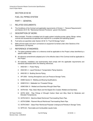
ASTM D2310 - Machine-Made Reinforced Thermosetting Resin Pipe. 11. ASTM D2996 - Filament-Wound Reinforced Thermosetting Resin Pipe. 12. ASTM D4021 - Glass-Fiber-Reinforced Polyester Underground Petroleum Storage Tanks. 13. NFPA 30 - Flammable and Combustible Liquids Code. University of Houston Master Construction Specifications Insert Project Name AE Project Number: Fuel Oil Piping 22 50 00 .
EXTERIOR WALLS Weathertightness AAMA 501-15 TF & F Air leakage ASTM E 283-04(2012) TF & F Water penetration ASTM E 331-00(2016) TF & F Structural performance ASTM E 330/330M-14 TF & F CURTAIN WALLING Impact resistance of opaque wall components - hard body impact tests BS 8200:1985 TF Impact resistance of opaque wall components - soft body impact tests BS 8200:1985 TF Impact resistance BS EN .
Brief introduction The main purpose of this guide for beginners is to have basic knowledge of Wordpress features and functionalities.
Beth Revis Első kiadás Könyvmolyképző Kiadó, Szeged, 2018 Millionyi_csillag2korr.indd 3 2018.05.15. 11:36 5 AJÁNLÁS „Minden kőben benne van a szobor, csak a felesleget kell lefaragni róla.” – Michelangelo – · Ezt a könyvet Merrileenek ajánlom, aki követ adott nekem, és Bennek meg Gilliannek, akik a kezembe adták a vésőt. Dei gratia. Millionyi_csillag2korr.indd .
CAMS/CMA Inter‐comparison of data characteristics and impact on NWP of FY‐3B SNPP and NOAA18 microwave observations Peiming Dong, Wei Han, Zeshuai Cai and Jiangping Huang NWPC/CMA ITSC19, March 26, 2014


