Liquid Containing Rectangular Concrete Tank Design
Liquid Containing Rectangular Concrete Tank Design
Liquid Containing Rectangular Concrete Tank DesignReinforced concrete tanks are used widely to collect and contain liquids from wastewater stations, process facilities,agricultural and environmental plants. In some cases the treatment to remove contaminants or solids also subjectsconcrete to additional requirements beyond structural design including the proper selection of materials, detailing,erection and construction practices to achieve maximum liquid tightness. Agricultural process byproduct requires arigorous management agenda for controlling pollution from surface runoff that may be contaminated by chemicals infertilizer, pesticides, animal slurry, crop residues, food, milk, blood, or irrigation water. In many cases, chemical andtemperature exposure has to be considered in the analysis and design of reinforced concrete tanks. This case studyfocuses on the design of a wastewater collection rectangular tank (pit) using the engineering software programs spWalland spMats. The tank under study is a 13 ft high partially buried open top fixed at the base to a 12” reinforced concretebase mat. The following figure and design data section and will serve as input for detailed analysis and design. ACI350 requirements are not evaluated in detail in this case study.Figure 1 – Rectangular Concrete Tank Plan and Elevation
CodeBuilding Code Requirements for Structural Concrete (ACI 318-14) and Commentary (ACI 318R-14)Code Requirements for Environmental Engineering Concrete Structures and Commentary (ACI 350R-06)ReferencespWall Engineering Software Program Manual v5.01, StucturePoint LLC., 2016spMats Engineering Software Program Manual v8.50, StucturePoint LLC., 2016Design DataTank Wall MaterialsTank Mat Foundation Materialsfc’ 4,000 psifc’ 4,000 psify 60,000 psify 60,000 psiTank Wall DimensionsTanks Mat Foundation DimensionsWidth 22 ftWidth 24 ftHeight 13 ftLength 24 ftThickness 12 in.Thickness 12 in.Applied Tank LoadsIn addition to wall and mat selfweights, the following figure shows all the loads applied to the tank:Figure 2 – Applied Loads (l and d indicated lateral and down respectively)Version: May-03-2019
Load CombinationsTable 1 – Wastewater Tank Ultimate Load CombinationTest Phase – Tank full without backfillTest1 1.4 D Fd 0.9 FlTest 2 0.9 D Fd 1.6 FlTest 3 1.2 D Fd 1.6 FlMaintenance Phase – Tank empty with backfillMaintenance1 0.9 D H d 1.6 H lMaintenance2 1.2 D H d 1.6 H lOperation Phase – Tank full with backfillOperation1 1.2 D Fd 0.9 H d 1.6 Fl 0.9 H lOperation 2 1.2 D H d 0.9 Fd 1.6 H l 0.9 FlVersion: May-03-2019
Contents1.Wastewater Rectangular Concrete Tank Wall Analysis and Design – spWall Software .12.Tank Wall Model Input .23.Tank Wall Result Contours .54.Tank Wall Cross-Sectional Forces .65.Maximum Tank Wall Displacement .96.Tank Wall Cross-Sectional Forces at Fixed Base . 107.Tank Wall Reactions At Fixed Based . 118.Tank Wall Required Reinforcement . 129.Tank Base Mat Analysis and Design – spMats Software . 1310. Tank Base Mat Model Input . 1311. Tank Base Mat Result Contours . 1512. Tank Base Mat Required Reinforcement . 1713. Soil Reactions / Pressure . 1814. Tank Base Mat Model Statistics . 1915. Tank Analysis Design Observation & Conclusions . 20Version: May-03-2019
1.Wastewater Rectangular Concrete Tank Wall Analysis and Design – spWall SoftwarespWall is a program for the analysis and design of reinforced concrete shear walls, tilt-up walls, precast walls,retaining walls, tank walls and Insulated Concrete Form (ICF) walls. It uses a graphical interface that enables theuser to easily generate complex wall models. Graphical user interface is provided for: Wall geometry (including any number of openings and stiffeners) Material properties including cracking coefficients Wall loads (point, line, and area), Support conditions (including translational and rotational spring supports)spWall uses the Finite Element Method for the structural modeling, analysis, and design of slender and nonslender reinforced concrete walls subject to static loading conditions. The wall is idealized as a mesh ofrectangular plate elements and straight line stiffener elements. Walls of irregular geometry are idealized toconform to geometry with rectangular boundaries. Plate and stiffener properties can vary from one element toanother but are assumed by the program to be uniform within each element.Six degrees of freedom exist at each node: three translations and three rotations relating to the three Cartesianaxes. An external load can exist in the direction of each of the degrees of freedom. Sufficient number of nodaldegrees of freedom should be restrained in order to achieve stability of the model. The program assembles theglobal stiffness matrix and load vectors for the finite element model. Then, it solves the equilibrium equations toobtain deflections and rotations at each node. Finally, the program calculates the internal forces and internalmoments in each element. At the user’s option, the program can perform second order analysis. In this case, theprogram takes into account the effect of in-plane forces on the out-of-plane deflection with any number ofopenings and stiffeners.In spWall, the required flexural reinforcement is computed based on the selected design standard (ACI 318-14 isused in this case study), and the user can specify one or two layers of wall reinforcement. In stiffeners andboundary elements, spWall calculates the required shear and torsion steel reinforcement. Wall concrete strength(in-plane and out-of-plane) is calculated for the applied loads and compared with the code permissible shearcapacity.For illustration purposes, the following figures provide a sample of the input modules and results obtained froman spWall model created for the rectangular wastewater tank walls in this case study.1
2.Tank Wall Model InputFigure 3 –Defining Tank Wall Loads and Load Combinations2
Figure 4 – Assigning Liquid and Soil Loads3
Figure 5 – Assigning Horizontal Wall RestraintsFigure 6 – Assigning Vertical Wall Restraints4
3.Tank Wall Result ContoursFigure 7 – Tank Wall Factored Axial Force ContourFigure 8 – Lateral Displacement Contour (Out-of-Plane)5
4.Tank Wall Cross-Sectional ForcesFigure 9 – Axial Load Diagram6
Figure 10 – Tank Wall Out-of-Plane Shear Diagram7
Figure 11 – Tank Wall Bending Moment Diagram8
5.Maximum Tank Wall DisplacementFigure 12 – Displacement at Critical Section (Service Combinations)Figure 13 – Displacement at Critical Section (Ultimate Combinations)9
6.Tank Wall Cross-Sectional Forces at Fixed BaseFigure 14 – Cross-Sectional Forces10
7.Tank Wall Reactions At Fixed BasedThe following wall reactions will be serve as the input to the mat foundation model and will be used as the partof the primary load cases in spMats. The reactions along the vertical wall edge have an equal and opposite forcefrom the opposite tank wall. A small in plane shear is generated causing a negligible axial stress in the walls.Figure 15 – Wall Reactions (Service Combinations)11
8.Tank Wall Required ReinforcementFigure 16 – Required Vertical ReinforcementFigure 17 – Required Horizontal Reinforcement12
9.Tank Base Mat Analysis and Design – spMats SoftwarespMats uses the Finite Element Method for the structural modeling, analysis and design of reinforced concreteslab systems or mat foundations subject to static loading conditions.The slab, mat, or footing is idealized as a mesh of rectangular elements interconnected at the corner nodes. Thesame mesh applies to the underlying soil with the soil stiffness concentrated at the nodes. Slabs of irregulargeometry can be idealized to conform to geometry with rectangular boundaries. Even though slab and soilproperties can vary between elements, they are assumed uniform within each element. Piles and/or supportingsoil are modeled as springs connected to the nodes of the finite element model. Unlike for springs, however,punching shear check is performed around piles.For illustration purposes, the following figures provide a sample of the input modules and results obtained froman spMats model created for the wastewater tank base mat in this case study.10. Tank Base Mat Model InputReactions are obtained from spWall model(Check Figure 15)Figure 18 – Importing Wall Reactions from spWall Model to the spMats Model13
Figure 19 – Defining Load CombinationsFigure 20 – Assigning Loads14
11. Tank Base Mat Result Contoursin.Figure 21 – Vertical (Down) Displacement Contourin.Figure 22 – Vertical (Up) Displacement Contour15
ksfFigure 23 – Soil Pressure Envelope Contourkip-ft/ftFigure 24 – Moment Contour along Y-Axis16
kip-ft/ftFigure 25 – Moment Contour along X-Axis12. Tank Base Mat Required Reinforcementin.2/ftFigure 26 – Required Reinforcement Contour along Y Direction (Bottom)17
in.2/ftFigure 27 – Required Reinforcement Contour along Y Direction (Top)13. Soil Reactions / PressureFigure 28 – Soil Service Reactions18
Figure 29 – Soil Pressure14. Tank Base Mat Model StatisticsSince spMats is utilizing finite element analysis to model and design the foundation. It is useful to track thenumber of elements and nodes used in the model to optimize the model results (accuracy) and running time(processing stage). spMats provides model statistics to keep tracking the mesh sizing as a function of the numberof nodes and elements.Figure 30 – Model Statistics19
15. Tank Analysis Design Observation & ConclusionsThe evaluation of the load combination requires a thorough evaluation of the construction, backfill, test,commissioning, maintenance, and repair stages required throughout the entire tank service life. The list used inthe this case study is just a partial set chosen for illustrationDesigner is advised to take the care required in exporting the wall reactions carefully to the base mat model toensure completeness and accuracy in the sign convention.The effect of buoyancy is not shown in this case study as the water table was assumed to be below the bottom ofthe tank. Additional loading considerations would be have to be added to adequately address this condition.20
1. Wastewater Rectangular Concrete Tank Wall Analysis and Design – spWall Software spWall is a program for the analysis and design of reinforced concrete shear walls, tilt-up walls, precast walls, retaining walls, tank walls and Insulated Concrete Form (ICF) walls. It uses a graphical interface that enables the
3- Differential surge tank: an orifice tank having a riser is called differential tank. 4- One- way surge tank: in a one way surge tank the liquid flows from the tank into the pipeline only when the pressure in the pipeline drops below the liquid level in the surge tank. 5- Closed surge tank: if the top of the tank is closed and there is
Seismic analysis of liquid-containing tanks differs from buildings in two ways: first, during seismic excitation, liquid inside the tank exerts hydrodynamic force on tank walls and base. Second, liquid-containing tanks are generally less ductile and have low redun-dancy as compared to buildings.Traditionally, hydrodynamic forces in a tank .
tank, this work was designed the refill sauce storage tank connection to the normal sauce storage tank to control level sauce in tank. m Fig.7. two liquid storage tank systems The purpose of this study is to control level in normal sauce tank. The apparatus, shows in Fig.7, consisting of normal sauce tank and one more refill sauce tank.
prevent tank uplifting, the following are minimum requirements for different types of common tank supports and surfaces upon which the tank shall be placed. Tank Supports – Tank supports shall be either (a) types that are included under the tank Listing (steel saddles welded to tank), or (b) 1.25" diameter
Fin – Input flow rate of the tank F out – Output flow rate of the tank H - Total height of the conical tank. R - Top radius of the conical tank h - Nominal level of the tank r - Radius at nominal level Fig3. Mathematical modeling of a conical tank The area of the conical tank is given by (3.1) R
A tank with its top open to the atmosphere contains liquid methanol (CH 3 OH, molecular weight 32g/mol) at the bottom of the tank. The tank is maintained at 30 C. The diameter of the cylindrical tank is 1.0 m, the total height of the tank is 3.0 m, and the liquid level at the bottom of the tank is maintained at 0.5 m.
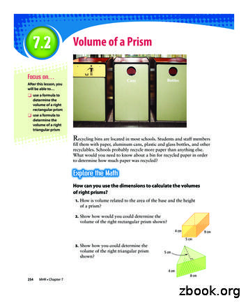
Solution a) Volume of a right rectangular prism area of rectangular base height of prism Volume of a right rectangular prism (length width) height V l w h V 2 3 4 V 24 The volume of the right rectangular prism is 24 cm3. b) A cube is also a right rectangular prism. Volume o
First course (on tables) Breads/rolls of many types (white, sour, rye, sesame, olive/caper, Italian season) Flavoured butters (honey, garlic, italian others .) Preserves (apple, pear, blackberry, salal) Two scalded milk cheese, one sweet, one savory Stout/Portwine cheese fondue Then: Soups/Stews - one beef/barley, one borshch and one bean pottage 2nd course Salmon Pie (head table gets .


