VT B-Series Installation Instructions (8-28-13)
11Condensing Unit Circuit Breakers (200/230V)10
Air Cooled Condenser Installation (VT100): Ice making systems with remote condensersare trapped internally. A trap leaving the compressor is not necessary. On vertical runs a shortradius “P” trap should be installed every 15’ to 20’ of vertical rise to facilitate oil flow. Horizontal runsshould be sloped in direction of refrigerant flow 1” for every 20’ of run. The condenser should besecurely mounted in a place capable of sustaining its weight.Condenser PipingNote: Dash lines indicate customer supplied piping.Recommended Traps11
Must solder with 45% silver solderLiquid return fromAir Cooled Condenser(7/8” line)Discharge gas toAir Cooled CondenserVT80 - 1 1/8”VT100 – 1 3/8”Teflon Seals:12A2600T01 – for 1 ¼”-12 adapter12A2600T03 – for 1 ¾”-12 adapterFemale Rota-lock Adapters:12A2396A0701 – for 1 ¼”-12 F x 7/8” Sweat(Return Line from condenser)12A2396A0601 – for 1 ¾”-12 F x 1 3/8” Sweat(Discharge to condenser)Note: Rota-lock maleadapter on ice machineRota-lock AdapterNote: Rota-lock adapterssupplied with machineVT80 & VT100 Condenser Refrigerant Line Connections12
Air Cooled Condenser Wiring: The air cooled condenser will be wired to the condensingunit control panel. Run two #14 AWG wires and a ground wire from the condensing unit controlpanel to the Air Cooled condenser control panel.To Ice Machinescondensing unitcontrol panel208/230V460VKramer VT100 Remote Air Cooled Condenser WiringNote: Fan control pressure switch is located in air cooled condenser control panel on VT100’swith remote condensers. On VT40’s and VT60’s, fan control pressure switch is location oncondensing unit (highside).13
KeepRite VT100, 200/230V Remote Air Cooled Condenser WiringNote: Fan cycling switch, FCC2 (Danfoss) for fan motor #2, is not factory set.Switch must be set in the field before startup. Cut Out 210 psi, Diff 25 psi.Use an accurate gage to set, not the scale on the pressure switch.14
KeepRite VT100, 400/460V Remote Air Cooled Condenser WiringNote: Fan cycling switch, FCC2 (Danfoss) for fan motor #2, is not factory set. Switch must beset in the field before startup. Cut Out 210 psi, Diff 25 psi15
Remote Control Panel (Optional): A remote panel can be added to control the icemachine. When installed, the jumper between 18 & X1 on the lowside control panel must beremoved and the “Selector Switch” in the “Ice” position.See table below for number, color, and size of wire to be run from the remote panel to the lowsidecontrol panel:Number of wires351Wire Size (AWG)14 (Red)14 (Blue)14 (Green)Remote Panel Layout16Wire #1, 2, Y012, 18, X1, X3, X4Ground wire
Complete Electrical Diagram with Remote Panel17
Model Evaporator Condensing Unit Model Skid Mounted VT40 520 lbs. 975 lbs. VT-40 1525 lbs. VT60 650 lbs. 1330 lbs. VT-60 2290 lbs. VT100 1,850 lbs. 400 lbs. (condenser) VT100 ----- . KeepRite VT100, 200/230V Remote Air Cooled Cond
SMB_Dual Port, SMB_Cable assembly, Waterproof Cap RF Connector 1.6/5.6 Series,1.0/2.3 Series, 7/16 Series SMA Series, SMB Series, SMC Series, BT43 Series FME Series, MCX Series, MMCX Series, N Series TNC Series, UHF Series, MINI UHF Series SSMB Series, F Series, SMP Series, Reverse Polarity
3 www.understandquran.com ‡m wQwb‡q †bq, †K‡o †bq (ف ط خ) rُ sَ _ْ یَ hLbB َ 9 آُ Zviv P‡j, nv‡U (ي ش م) اْ \َ َ hLb .:اذَإِ AÜKvi nq (م ل ظ) َ9َmْ أَ Zviv uvovj اْ ُ Kَ hw ْ َ Pvb (ء ي ش) ءَ Cﺵَ mewKQy ءٍ ْdﺵَ bِّ آُ kw³kvjx, ¶gZvevb ٌ یْ"ِKَ i“Kz- 3
SMP Series page 73 FAKRA Connectors page 77 BNC Series page 79 TNC Series page 108 N Series page 133 7/16 Series page 149 UHF/MINI-UHF Series page 159 F Series page 167 Twin Series page 175 D-sub Series page 179 FME Series page 181 1.0/2.3 Series page 183 1.6/5.6 Series page 189 Filtered Series page 197
5.3. STAFInst Uninstall 6. Platform Installation Notes 6.1. Linux installation 6.2. AIX installation 6.3. HP-UX IA64 64-bit installation 6.4. IBM i 32-bit (previously known as i5/OS or OS/400) installation 6.5. z/OS installation 6.6. FreeBSD installation 6.7. Mac OS X installation 6.8. Solaris installation 7. Environment Variable Settings 7.1.
RESTAURANT SERIES OPERATION MANUAL TABLE OF CONTENTS 1 INSTALLATION INSTRUCTIONS 1 OPERATING INSTRUCTIONS 2 MAINTENANCE INSTRUCTIONS 4 WARRANTY 6 INSTALLATION INSTRUCTIONS Installation of the equipment should be performed by qualified, certified, and authorized personnel who are familiar and experienced with local installation codes.
5 Series E39 5 Series E60/E61 5 Series F10/F11/F18 5 Series GT(F07) 6 Series E63/E64 6 Series F06/F12/F13 7 Series E38 7 Series E65/E66/E68 7 Series F01/F02/F03/F04 I Series I01/I12 X Series X3_E83 X Series X5_E
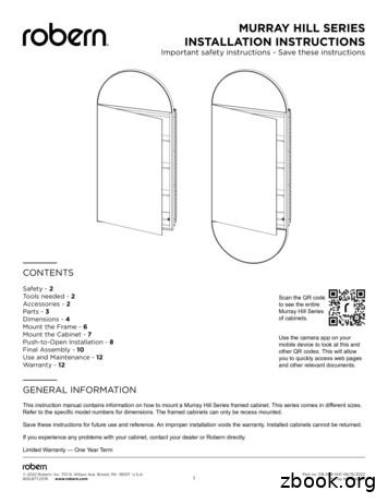
Murray Hill Cabinet 2022 Robern Inc 701 N Wilson Ave Bristol PA 19007 USA 8008772376 www.robern.com MURRAY HILL SERIES INSTALLATION INSTRUCTIONS Important safety instructions - Save these instructions Safety - 2 Tools needed - 2 Accessories - 2 Parts - 3 Dimensions - 4 Mount the Frame - 6 Mount the Cabinet - 7 Push-to-Open Installation - 8
RP / RPc Series Installation Instructions c. 2 1217 3 ay ar 1835 adonaway.com 2 Fan Installation & Operating Instructions Please Read and Save These Instructions. . If used, the recommended speed control is Pass & Seymour Solid State Speed Control. 2.0 INSTALLATION The RP / RPc Series Fans can be mounted indoors or outdoors. (It is suggested .


