Circuit Diagrams And Symbols (1) - WordPress
Name:Circuit SymbolsWe remember how we put the circuits together by using a diagram or drawing asketch. In order to save time and ensure that sketches are accurate, scientists cameup with a novel way of showing the components of a circuit using special symbols.These symbols are used all over the world and help scientists, engineers andtechnicians to draw or record circuits more quickly and accurately.ComponentSketchSymbolWireLight bulbBattery (cell)SwitchClosed circuitOpen circuit e-classroom 2013www.e-classroom.co.zaGRADE 6Grade 6: Term 3: Natural Sciences and Technology-Electric circuitsCircuit diagrams and symbols (1)
Drawing CircuitsIn the space provided, draw your own circuit using symbols from the previousworksheet. Remember to label your symbols.This a circuit diagram. This is a simple and quick way to represent an electric circuit.The circuit has a battery, a bulb and a switch, which are all connected with electricwires.Did you draw straight circuit wires or were they a little curved and bent?Although we draw the wires as straight lines in a circuit diagram, in real life, the wiresare not straight.Your circuit should look like this:batteryswitchlight bulbNow draw as many different circuits as you can. Here are some ideas:A circuit with 1 cell and 2 bulbsA circuit with 2 cells and 2 bulbA circuit with 3 cells and 3 bulbsA circuit with 3 cells, a bulb and an open switchA circuit with 1 cell and 2 bulbs and a closed switch. The switch must be in betweenthe bulbs. e-classroom 2013www.e-classroom.co.zaGRADE 6Grade 6: Term 3: Natural Sciences and Technology-Electric circuitsCircuit diagrams and symbols (2)
Grade 6: Term 3: Natural Sciences and Technology-Electric circuitsGRADE 6Electric circuits (1)Name:Simple CircuitsRevision Exercise:Explain the meaning of electricity:What material do we need to make a simple circuit?What is the difference between a closed and open electrical circuit?Research Activity:Think of the world that we live in today. One of the things that we are in touch withon a daily basis is electricity. Write down at least six uses of electricity in your school.FUN ACTIVITY: Making your Own Simple Circuitsource of energy: battery (input energy)conducting material: wiredevice: light bulb (output energy) e-classroom 2013www.e-classroom.co.za
Instructions:Connect the battery to the bulb using one wire in four different ways. You can placethe bulb on top of, below and next to the battery.Record your findings:l Draw a picture of how you connected the light bulblDid the light bulb light up? Answer yes or no:lIf your answer is “no”, why do you think it didn’t light up?In conclusion, when the light bulb lit up, you constructed a simple electrical circuit.A circuit is a complete, unbroken pathway for electricity to move along (transfer)from the source, which in this case is the battery (input energy) to the device, thelight bulb (output energy).Now try and do the same exercise, using two wires. What did you discover?Key learning points:l Simple circuits consist of three different components (parts of a whole):1. A source of electrical energy, such as the battery2. Conducting material, along which the electricity is transferred such as theelectric wires3. A device that transfers the energy for a useful purpose, such as the bulb thatprovides light e-classroom 2013www.e-classroom.co.zaGrade 6: Term 3: Natural Sciences and Technology-Electric circuitsGRADE 6Electric circuits (2)
Electrical CurrentElectricity is transferred from the source (battery) to the device (light bulb). Anotherway of saying this is that the electricity “flows” from the source to the bulb to make itlight up. This is called an “electrical current”.The charge is already in the wires (carried by billions of tiny particles calledelectrons). This charge is evenly spread out through the wires. When the bulb doesnot light up, we have not made a proper or complete pathway for the electricity toflow and so the electrical current is broken or incomplete.It’s like a bicycle chain. The links are like the charge, the wheel is like the bulb andyour feet are like the battery. As soon as you start pedalling, the back wheel startsto move. This is because turning the pedals makes all the links move at once. It’s notjust the links nearest your feet that move.Feet pedalling (Battery)KEY WORDScomponentelectrical currentflowThe Electrical SwitchWe know that there is a flow of electrical current through the circuit which lights upthe bulb. When that current is broken, the flow of electrical charge to the bulb isbroken, thus resulting in the bulb not lighting up.We can deliberately cut off the electrical current to a device, using a switch. Aswitch is used to turn an electrical circuit on and off.Fill in the missing words:The switch is used to or an electrical circuit. When the e-classroom 2013www.e-classroom.co.zaGrade 6: Term 3: Natural Sciences and Technology-Electric circuitsGRADE 6Electric circuits (3)
switch is on, the circuit is and when the switch is thecircuit is open. Electrical current exists in the circuit when it is closed, but when itis open, there is no current in the circuit. The switch determineswhether the circuit is open or closed.FUN ACTIVITY: Create a Simple Electrical Circuit with a SwitchMaterials you need:l A bulbl 1 x battery (1.5v)l cardl staples (x2)l paper clipl sticky tapel wireMethod:l Punch the staples through the card about 2 cm apartl Tape the wire to the plus end ( ) of the battery and the other to the minus (-) endl Attach the wire taped to the (-) end of the battery to the bottom of the bulbl Connect the wire taped to the end of the battery to one of the staplesl Use the third wire to join the second staple to the side of the bulbl Use the paperclip to touch both staplesYou will notice that:When you turn the paper clip so that it touches both staples, the circuit is open andthe bulb lights up. If you move the paper clip away from one of the staples, thecircuit is broken (closed) and the light goes out.Write your own conclusion in the space below: e-classroom 2013www.e-classroom.co.zaGrade 6: Term 3: Natural Sciences and Technology-Electric circuitsGRADE 6Electric circuits (4)
The Electrical Switch We know that there is a flow of electrical current through the circuit which lights up the bulb. When that current is broken, the flow of electrical charge to the bulb is broken, thus resulting in the bulb not lighting up. We can deliberately cut off the electrical current to a device, using a switch. A
a time period. There are seven behavioral diagrams: Use Case Diagrams, Activity Diagrams, State Machine Diagrams, Communication Diagrams, Sequence Diagrams, Timing Diagrams and Interaction Overview Diagrams. UML 2 has introduced Composite Structure, Object, Timing and Interaction Overview diagrams.
node diagrams (N diagrams), node-link diagrams (NL diagrams) and node-link-groups diagrams (NLG diagrams). Each of these diagrams extends the previous one by making more explicit a characteristic of the input data. In N diagrams, a set of objects is depicted as points in a two or three dimensional space; see Figure1a. Clusters are typically .
Custom Symbols underneath Basic Symbols in the Symbols pane of the Graphics Editor. Upon drill-down, further layers of Custom Symbols open up. Level 1: This level contains folders and symbols such as region name folders, the Symbols folder, and several .json files, amongst others. In the Metasys UI, expand the Custom Symbols accordion
Class Diagrams etc. (e.g. Component Diagrams) Dynamic / Behavioral Modeling: capturing execution of the system Use Case Diagrams Sequence Diagrams State Chart Diagrams etc. (e.g. Activity Diagrams) UML Diagrams Models: high-level class relations Components: Class (rectangle) - Upper section: name of the class
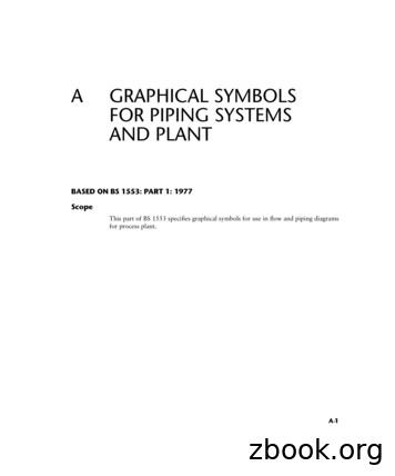
A GRAPHICAL SYMBOLS FOR PIPING SYSTEMS AND PLANT BASED ON BS 1553: PART 1: 1977 Scope This part of BS 1553 specifies graphical symbols for use in flow and piping diagrams for process plant. A-1. Symbols (or elements of Symbols) for Use in Conjunction with Other Symbols Mechanical linkage Weight device
Symbols for Fire Control Plans Symbols Related to Life-Saving Appliances and Arrangements Symbols from the Code on Alarms and Indicators, 1995 How to find the Symbols Files containing the Symbols in digital form Tips on the use of the Symbols in digital form and note on colours of the digital images Address of IMO Publications Colophon
circuit protection component which cars he a fusible link, a fuse, or a circuit breaker. Then the circuit goes to the circuit controller which can be a switch or a relay. From the circuit controller the circuit goes into the circuit load. The circuit load can be one light or many lights in parallel, an electric motor or a solenoid.
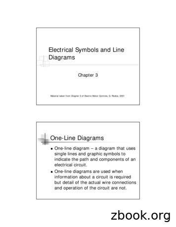
Material taken from Chapter 3 of Electric Motor Controls, G. Rockis, 2001 One-Line Diagrams One-line diagram – a diagram that uses single lines and graphic symbols to indicate the path and components of an electrical circuit. One-line diagrams are used when information about a circuit is required but detail of the actual wire connections


