Ball Valve Process And Instrument Version Model BV
AccessoriesBall valveProcess and instrument versionModel BVWIKA data sheet AC 09.28for further approvalssee page 7Applications Oil and gas industry, chemical and petrochemicalindustries, power plants First shut-off valve for pressure tap to local instrumentinstallation, media distribution, drain or vent pipelines Direct connection of pressure measuring instruments topipelines or vessels For gaseous, liquid, aggressive and highly viscous media,also in aggressive environmentsSpecial features Safety factor 4:1 for pressurised parts High-quality machining guarantees smooth operation withFig. left: Model BV, process version, square designFig. right: Model BV, instrument version, round designlow torque and low wear Leak-tested tightness in accordance with BS6755 /ISO 5208 leakage rate A Large selection of materials and configurations available Customer-specific combination of valves and instruments(hook-up) on requestDescriptionThe simple and robust design, with a safety factor of 4:1,enables model BV ball valves a wide spectrum of use.This ranges from the simple distribution of compressed airthrough to demanding applications in the oil and gas industry.The process version of the ball valve has been designed tomeet the requirements of the process industry, in particularfor natural gas and aggressive media applications.The valve design and the high-quality sealing materialsensure high durability and tightness.For applications with liquid or gaseous media, ball valves arerecommended due to easy cleaning of the straight-throughinternal bore.The super-finished machining of the internal parts allows avery smooth and precise operation, even at high pressuresand after long periods without valve operation. The surfacefinish is also minimising corrosion with aggressive media andmakes it easier to clean.WIKA data sheet AC 09.28 05/2020Data sheets showing similar products:Monoflange, process and instrument version; model IVM; data sheet AC 09.17Monoblock, with threaded connection; models IBM2 and IBM3; data sheet AC 09.24The ball valve can be mounted, depending on the installationconditions, directly onto a pipeline or in a control panel, or forthe connection of several measuring instruments at the samelocation.Page 1 of 11
SpecificationsModel BVStandards usedDesign ASME B16.34, valves - flanged, threaded and welding endMSS SP-99, valves for measuring instrumentsASME BPVC section VIII, rules for construction of pressure vessels division 1ASME B31.1, power pipingASME B31.3, process pipingISO 17292, metal ball valves for petroleum, petrochemical and allied industriesASME B16.5, pipe flanges and flange fittingsASME B1.20.1, pipe threads, general purpose (inch)Tests API 598, valve inspection and testingISO 5208, pressure testing of metallic valves with leakage rate AMSS SP-61, pressure testing of valvesDIN EN 12266-1, pressure tests, test procedures and acceptance criteria for industrial valvesAPI 607, ISO 10497, BS 6755-2, type test for fire safetyMaterial requirements NACE MR0175 / ISO 15156, use in H₂S-containing environments in oil and gas production NORSOK M-630, specification for use in pipelines (Norway)MarkingASME B16.34, valves - flanged, threaded and welding endVersion(see from page 4)Instrument version Round design Square designProcess version Square design Multiport designNominal pressure 6,000 psi [413 bar] 10,000 psi [690 bar]Nominal width (DN) Valve bore size 10 mm [0.394 in] 20 mm [0.787 in]Pressure-temperature limits(for diagram, see page 6)The limits for operating pressure and temperature depend on the version and the sealing material.¼"3/8"½"¾"1"Connection type Threaded connection per ISO 228-1, code GThreaded connection per ANSI / ASME B1.20.1, code NPTConnection for welded sleeveConnection for butt weld connectionSmooth pipe endCompression fittingFeatures Free-floating ballAntistatic designBlow-out proof valve spindleSelf-relieving valve seatsOpening and closing direction marked on lever handleQuarter-turn of lever handle opens/closesLocking pin limits rotation angle of lever handleBubble-tight shut-offBidirectional flow with minimal pressure dropHydrostatically testedMounting holes for panel mounting (option)Mounting holes and valve stem for actuators (option)WIKA data sheet AC 09.28 05/2020Page 2 of 11
MaterialsWetted partsStainless steel 316LDuplex F51 (1.4462)Super Duplex F55 (1.4501)Hastelloy C276 (2.4819)Monel 400 (2.4360)Stainless steel 6Mo (1.4547)Alloy 625 (2.4856)Alloy 825 (2.4858)Valve body and fittings, ball,valve stem Ball valve seat 1) 2) PEEK, temperature range: -55 . 260 C [-67 . 500 F] HTT (high-temperature thermoplastic), temperature range: -55 . 350 C [-67 . 662 F]Non-wetted partsLocking pin, screwsStainless steel 316/316LLever handleStainless steel 316/316L, PVC coated1) Other materials available on request2) For the process version, additional compressed graphite 99 % is used (with certification for fire protection)Instrument versionLocking pinLever handleValve stem with sealing packingBallMetal-to-metal seatSealing ring of valve bodyValve bodyProcess versionLocking pinLever handleAntistatic designValve stemConductiveconnection betweenball and valve stemBallValve stem with sealing packingBallSeat with soft sealing ringMetal sealing ringLocking pinValve bodyWIKA data sheet AC 09.28 05/2020Page 3 of 11
Standards usedInstrument version MSS SP-99, valves for measuring instrumentsProcess version ASME B16.34, valves - flanged, threaded and welding end API 607, ISO 10497, BS 6755-2, type test for fire safetyInstrument versionRound designSquare design, with mounting holes for panelmounting (option)Process versionSquare designWIKA data sheet AC 09.28 05/2020Multiport designPage 4 of 11
OptionsAnti-tamper version with padlockExtended lever handleMounting holes and valve stem foractuatorsExtended valve body, suitable forflushing ringsMounting holes for panel mounting(option)Panel hole patternB A DNDimensions in mm [in]1/4"24 [0.94]AB35 [1.38]30 [1.18]5 [0.28]3 [0.12]3/8"24 [0.94]35 [1.38]30 [1.18]5 [0.28]3 [0.12]1/2"24 [0.94]35 [1.38]30 [1.18]5 [0.28]3 [0.12]¾"46 [1.81]50 [1.97]45 [1.77]7 [0.27]3 [0.12]1"46 [1.81]50 [1.97]45 [1.77]7 [0.27]3 [0.12]WIKA data sheet AC 09.28 05/2020CDPanelPage 5 of 11
Pressure-temperature diagram700(10153)PEEK600(8702)HTTPressure in bar 0Temperature in C ( F)Sealing materialBall valve seatPEEK 1)HTT (high-temperaturethermoplastic)Max. permissible operatingpressure in bar at temperaturein CMax. permissible operatingpressure in bar at temperaturein C276 bar at 260 C4,000 psi at 500 F690 bar at 38 C10,000 psi at 100 F250 bar at 350 C3,655 psi at 662 F690 bar at 38 C10,000 psi at 100 F1) PolyetheretherketoneThe minimum design temperature is -55 C [-67 F]. For permanently low operating temperatures of -55 C [ -67 F] aspecial design is required.WIKA data sheet AC 09.28 05/2020Page 6 of 11
ApprovalsLogoDescriptionEAC (option)Machinery directiveCountryEurasian Economic CommunityManufacturer‘s information and certificationsLogo Description-PMI 1) test certificate (option)All wetted parts-Type tested for fire safety in accordance with API 607, ISO 10497, BS 6755-2 2)1) Positive material identification2) Valid only for process versionCertificates (option) 3.1 inspection certificate per EN 10204- Material certificate for all wetted parts per NACE MR0103/MR0175- Confirmation of pressure tests per API 598 3)3) Shell test: 15 s test duration with 1.5 times the permissible working air pressureSeat test: 15 s test duration with 6 bar air/nitrogenWIKA data sheet AC 09.28 05/2020Page 7 of 11
Dimensions in mm [in]Model BV, instrument version, round design, 3-partNominal pressure: 6,000 psi [413 bar]ABCEDDNPartsDimensions in mm [in]1/4"310 [0.394]1/2"1"Bore sizeAB77 [3.031]93 [3.661]72 [2.835]32 [1.26]128 [5.039]CDE3/8"310 [0.394]128 [5.039]77 [3.031]93 [3.661]72 [2.835]32 [1.26]310 [0.394]131 [5.157]77 [3.031]93 [3.661]72 [2.835]32 [1.26]¾"320 [0.787]197 [7.756]120 [4.724]140 [5.512]113 [4.449]60 [2.362]320 [0.787]200 [7.874]120 [4.724]140 [5.512]119 [4.685]60 [2.362]DEModel BV, instrument version, round design, 2-partNominal pressure: 10,000 psi [690 bar]ABCEDDNPartsDimensions in mm [in]1/4"210 [0.394]Bore sizeAB94 [3.701]132 [5.197]82 [3.228]45 [1.772]3/8"210 [0.394]164 [6.457]94 [3.701]132 [5.197]82 [3.228]45 [1.772]1/2"210 [0.394]164 [6.457]94 [3.701]132 [5.197]82 [3.228]45 [1.772]¾"220 [0.787]188 [7.402]129 [5.079]140 [5.512]104 [4.094]68 [2.677]1"220 [0.787]188 [7.402]129 [5.079]140 [5.512]107 [4.213]68 [2.677]WIKA data sheet AC 09.28 05/2020164 [6.457]CPage 8 of 11
Model BV, instrument version, square designAEBCDNominal pressure: 6,000 psi [413 bar]DNPartsDimensions in mm [in]1/4"310 [0.394]1/2"1"Bore sizeAB77 [3.031]93 [3.661]65 [2.559]32 [1.26]122 [4.803]CDE3/8"310 [0.394]122 [4.803]77 [3.031]93 [3.661]65 [2.559]32 [1.26]310 [0.394]127 [5]77 [3.031]93 [3.661]72 [2.835]32 [1.26]¾"320 [0.787]188 [7.402]120 [4.724]140 [5.512]104 [4.094]60 [2.362]320 [0.787]190 [7.48]120 [4.724]140 [5.512]110 [4.331]60 [2.362]Nominal pressure: 10,000 psi [690 bar]DNPartsDimensions in mm [in]1/4"210 [0.394]1/2"1"Bore sizeAB94 [3.701]132 [5.197]82 [3.228]40 [1.575]164 [6.457]CDE3/8"210 [0.394]164 [6.457]94 [3.701]132 [5.197]82 [3.228]40 [1.575]210 [0.394]164 [6.457]94 [3.701]132 [5.197]82 [3.228]40 [1.575]¾"220 [0.787]188 [7.402]120 [4.724]140 [5.512]104 [4.094]65 [2.559]220 [0.787]188 [7.402]120 [4.724]140 [5.512]107 [4.213]65 [2.559]WIKA data sheet AC 09.28 05/2020Page 9 of 11
Model BV, process version, square designNominal pressure: 10,000 psi [690 bar]AEBCDDNPartsDimensions in mm [in]1/4"210 [0.394]164 [6.457]94 [3.701]132 [5.197]82 [3.228]40 [1.575]1/2"Bore sizeABCDE3/8"210 [0.394]164 [6.457]94 [3.701]132 [5.197]82 [3.228]40 [1.575]210 [0.394]168 [6.614]94 [3.701]132 [5.197]87 [3.425]40 [1.575]¾"220 [0.787]175 [6.89]94 [3.701]132 [5.197]93 [3.661]40 [1.575]Model BV, multiport designNominal pressure: 10,000 psi [690 bar]CEBADDNClassPartsDimensions in mm [in]1/4"10,000210 [0.394]10,00023/8"Bore sizeALCDE10 [0.394]182 [7.165]94 [3.701]132 [5.197]117 [4.606]40 [1.575]WIKA data sheet AC 09.28 05/2020182 [7.165]94 [3.701]132 [5.197]117 [4.606]40 [1.575]Page 10 of 11
Ordering informationModel / Version / Nominal pressure / Nominal width (DN) / Options05/2020 EN 05/2020 WIKA Alexander Wiegand SE & Co. KG, all rights reserved.The specifications given in this document represent the state of engineering at the time of publishing.We reserve the right to make modifications to the specifications and materials.WIKA data sheet AC 09.28 05/2020Page 11 of 11WIKA Alexander Wiegand SE & Co. KGAlexander-Wiegand-Straße 3063911 Klingenberg/GermanyTel. 49 9372 132-0Fax 49 9372 132-406info@wika.dewww.wika.de
MSS SP-99, valves for measuring instruments ASME BPVC section VIII, rules for construction of pressure vessels division 1 ASME B31.1, power piping ASME B31.3, process piping ISO 17292, metal ball valves for petroleum, petrochemical and allie
» 2" Ball Valve - H2O2 Specification » 2" - Offshore Specification » 2" Full Bore Ball Valve - Gas » 80mm PFA Lined Flanged Ball Valve » 3" - 3" BSP Outlet » 3" - » 4" - Rail » Socket / In-Line Blacko Airline Ball Valve Blacko Airline Ball Valve Blacko Airline Ball Valve Blacko Airline Ball Valve Airline Valve Blacko Ball Valve
the flow rate and pressure. To select the correct valve to fulfill these functions properly, an outline of the different types of valves and their features is given below. Butterfly valve Butterfly valve and globe valve Butterfly valve and ball valve Butterfly valve and gate valve Check valve Gate valve Globe valve Ball valve Valve shaped like a
Manual ball valve with electric feedback unit in the multi-functional module Solvent cement socket. Threaded socket. Standard ball valve Ball valve with lockable handle Ball valve with pneumatic actuator and manual override Ball valve with electric actuator Ball valve with handle extensio
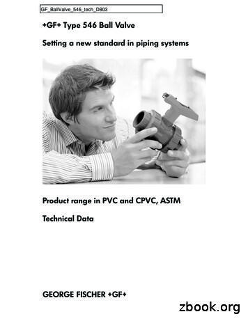
Ball Valve Type 546 Ball Valve Type 375 COLORO Compact Ball Valve Type 355 COLORO Ball Valve Type 353 Metering Ball Valve Type 523 True union ball valve. Maintenance free. Guaranteed performance. Tested 50,000 cycles. Can be converted to actu-ated in-line. Handle extension, silicone-free and Control Ball feature are available options.
through 24) V150, V200 and V300 Vee-Ball control valves. The Vee-Ball valve combines globe valve ruggedness with the efficiency of a rotary valve. The Vee-Ball valve is a segmented ball valve which features a contoured segmented V-Notch ball. A shearing action between the V-notch ball and the ball seal (figure 1) promotes smooth, nonclogging .
When choosing the right three-way ball valve, it is important to both understand the key three-way valve design options and plan how the valves will be used. First, some basics. What is a three-way ball valve? Three-, four- and five-way ball valves are called multi-port valves. The three-way ball valve is the most common multi-port ball valve.
Ball Screw Selection White Paper Ball Screw Basics A ball screw assembly consists of a ball screw and a ball nut with recirculating ball bearings. (Figure 1) The interface between the screw and the nut is made by ball bearings that roll in matching forms in the ball screw and ball nut. The load on the ball screw
BI-TORQ Valve Atatin P.O. Bx 309 La Fx, IL 60147 tel 630-208-9343 ax 630-232-6235 e-ail salesitr.c-4-MZ-2P BronZe Ball ValVe 2-Piece Full Port BronZe Ball ValVe Full port bronze ball valve 1/4" through 3" Blow-out proof stem Chrome plated brass ball ValVe Features PART # NAME MATERIAL QTY 1 BODY BRONZE 1 2 BALL CHROME PLATED


