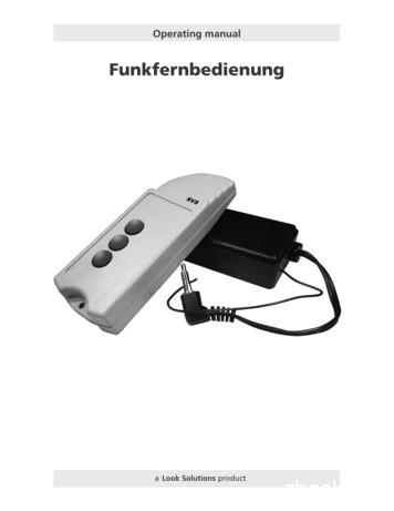
Radio Remote Manual Tiny Fogger Viper NT Fog Machine
Operating manualFunkfernbedienung1a Look Solutionsproduct
Set of Equipment supplied– 1 receiver with mini-stereo-jack-plug or 3-pin-XLR-plug– 1 radio transmitterPlease check whether all the products you ordered are supplied.2
Contents1. Introduction182. The Transmitter2.1 Operation2.2 Coding2.3 Replacing the battery193. The Receiver3.1 Operation3.2 Channel access3.3 Coding3.4 Wiring of the connectors214. System range235. Technical Data246. Warranty Conditions253
1. IntroductionThe UHF radio system consists of a radio transmitter and one or several receivers.The operating frequency of the system is 433 MHz.By means of the radio transmitter you have the ability to address three channelswhich can either be three individual receivers or three receiving groups. Thenumber of the receivers per channel is not limited.The system has 256 coding options.4
2. The transmitter2.1 OperationThe radio transmitter is in a usable state with the supplied battery inserted.To transmit press one of the three buttons (1,2 or 3). If the key is pressed toobriefly, the receiver ignores the command. For receiving several consecutive codecycles must be identical before a command is recognized as valid.While sending the transmitter should be in your hand and held away from yourbody. If your hands clasp the antenna integrated in the round part of the casingor when you approach too big a metal surface/area, the range may be reducedand should therefore be avoided.TransmitterfrontTransmitterbackButton 1Button 24Button 3LookSolutions made in Germany2.2 CodingThe system offers 256 codeing options. The setting is made by means of Dilswitches.To change the coding set by the factory, open the apparatus by loosening thescrews [4] with a suitable screwdriver and dismantle the two halves of the casing.Using a ball-point pen you can now set your individual code.5
2. The TransmitterEach of the 8 slide switches has three operating positions: 0 –.When delivered the switches are in position 0.For coding only switch positions 0 and – may be used.The switch positions are not recognized by the receiver.Reference: The relevant receiver(s) as well as the transmitter must be encodedidentically (same switch position).–0 –1234567812345678 –0 When deliveredall switches arein position 0 Example forindividualadjusting(only position0 and –)–2.3 Replacing the BatteryThe life of the battery depends on the use of the radio transmitter. If the rangeis strongly reduced or transmission is not possible, the battery must be replaced.Only use standard 12 V-alkaline batteries.Loosen both the screws [4] with a suitable screwdriver and dismantle the twohalves of the casing. Remove the used-up battery and insert the new one. Payattention to polarity and test contact of the battery by trying to transmit.6
3. The Receiver3.1 Operation1The receiver is equipped with a stereo jack plug[1] or a 3-pin-XLR-plug (it depends on which machine it will control) and a short wire antenna [2].Plug the plug [1] into the corresponding socketof the machine to be controlled.2In case of the Tiny-Fogger/Tiny Compact:Plug the radio remote into the socket beforeyou connect the Tiny-Fogger or Tiny Compact tothe battery! Otherwise it could happen that themachine starts to fog automatically.The receiver now receives the necessary powerfrom the the machine and is ready for operation.Pressing of button 1 of the radio transmitter nowstarts the fogging process.Note: The antenna should be in upright posi-tionand should not be concealed by conductive objects.3.2 Channel Access/Selecting the ChannelFor this purpose open the receiver by removingthe cover plate. This is only embedded and canusually be taken off without any tool. A slim slotscrewdriver, for example, enables you to remove thecover.Channel 3Channel 2Channel 1Should several units be required to be addressed on different channels (1,2 or3), the jumper [3] within the receiver must be replugged.3The jumper [3] is red and when supplied it is inposition channel 1, i.e. the receiver reacts whenbutton 1 of the radio transmitter is pressed.By moving the jumper to one of the two alternative positions, the receiver reacts to the accordingposition (press button 2 or 3 of the radio transmitter).7on12345678
3. The Receiver3.3 CodingShould the radio system be readjusted to a different coding other than set bythe factory, the receiver as well as the manual transmitter need to be adjusted.To do so, open the receiver as described in point 3.2. You can now set yourindividual code with a ball-point pen on the eight slide switches.The slide switches of the receiver have 2 positions: ON and OFF.When supplied all switches are in the OFF position.Reference: The coding must be the same on the receiver (same switch position)as with the transmitter that goes with it. If only switch 2 is changed to ON, onlyswitch 2 must also be modified in the transmitter (see section 2.2.).3.4 Wiring of the connectors3-pin XLR malePin 1 GroundPin 2 0 - 10 V DC ( )Mini-Stereo jack (for TINY-FOGGER)Sleeve GroundRing switch o/pPin 3 12 V DC ( ) inputTip 12 V DC ( ) input8
4. System RangeThe radio remote control is designed for a long range of 100 meters if conditionsare ideal. The manual transmitter even passes through walls or reinforced concreteconstructions. The maximum range is achieved only in case of visual contact withthe receiver and with no radio-frequency interference‘s.Possible causes for reduced range: Building/Construction of any kind or vegetation affect the range. The distance of the transmitter to the body as well as the distance of the receiverto other conducting areas or objects (the soil included) affects strongly theradiation characteristic and thus influences the range. The antenna of the receiver should be placed upright and be vertical from thecontrol unit. Winding the antenna affects reduces the range. An antenna extension lead always causes an insertion loss and consequentlyreduces the received power. Radio noise in non-rural areas can be relatively high, through which the signalto-noise becomes reduced and thus the range is limited. If another unit usingthe same frequency is in operation near by, the radio receiver will not work orit will not receive the correct code. When the receiver is operated near poorly-shielded personal computers (andwith most personal computers this is the case) or similar units which produceradio interference, strong range forfeits can also occur or even result in theapparent disturbance of the receiver. No adjustments should be carried out to the transmitter or the receiver.9
5. Technical DataTransmitterTransmitting frequencyRadiated power (ERP)ModulationNumber of channelsCoding optionsVoltage supplyRange of working temperatureDimensions (L x W x H)433, 920 MHz /– 150 KHz 25 mW ( 14 dBm)100% AM325612 V DC (battery)0 C to 65 C10 x 3.7 x 1.9 cmReceiverReceiving frequencyResponsivityDemodulationVoltage supplyCoding optionsChannel access/selection (Jumper)Dimensions (L x W x H)433, 920 MHz /– 150 KHz1 µVlog. AM-demodulator12 V DC via stereo jack plug25637.7 x 3.8 x 2.0 cm10
6. Warranty ConditionsFor the Radio remote Look‘ guarantee is:1. Free of charge, subject to the following conditions (No. 2 - 6) we will repair any defect orfault in the unit if it is caused by a proven factory fault and has been advised immediatelyafter appearance and within 24 month of delivery to the end user. Insignificant deviationsof the regular production quality does not guarantee replacement rights, nor do faultsor defects caused by water, by generally abnormal environment conditions or ForceMajeure.2. Guarantee Service will be done in the following way: Faulty parts will be repaired orreplaced (our chioce) with correct parts. Faulty units have to be brought to us or ourservice centres or to be sent to us or our service centres at customer‘s expenses. Theinvoice and/or receipt showing the purchase date and the serial number has to comewith the faulty unit, otherwise this will not be guarantee service. Replaced parts becomeour property.3. The customer looses all rights for guarantee services, if any repairs or adjustments aredone to the units by unauthorized persons and/or if spare parts are used which are norapproved by us. Also non compliance with the instructions in this manual or mistakes byincorrect handling/treating of the machine will lead to a loss of guarantee and also anyfaults and damages caused by undue force.4. Any freight costs arrising in connection with the guarantee services have to be born bythe customer.5. Guarantee services do not cause an extension of the guarantee time or the start of anew guarantee time. The warranty for replaced parts ends with the guarantee time ofthe whole unit.6. If a defect/fault can not be repaired by us in a satisfactory time, we will, within 6 monthsafter sale of the unit, on choice of the customer, either: replace the whole unit for free or refund the lesser value or take back the whole unit and refund the purchase price, but not more than the usualmarket price at the time of the refund.7. Further claims, especially for damages, losses etc. outside the unit are excluded.Other guarantee regulations may be valid outside Germany. Please check with your dealer!11
a Look Solutionsproduct12
Radio Remote Manual Tiny Fogger Viper NT Fog Machine Author: Look Solutions Subject: Radio Remote Manual Tiny Fogger Viper NT Fog Machine Keywords: Radio Remote Manual Tiny Fogger Viper NT Fog Machine Created Date: 4/11/2006 1:47:19 PM
Jul 09, 2015 · Tiny-Fogger/Tiny F07, Tiny-Compact/Tiny C07 Tiny-Fluid 42 Tiny FX Tiny-Fluid 42 Tiny S Tiny-Fluid 43 Unique 2.1 Unique-Fluid 43 Viper NT Quick-Fog Fluid 44 Viper NT Regular-Fog Fluid 45 Viper NT Slow-Fog Fluid 46 Martin K-1 Froggy’s Fog K-razy Haze Fluid 47 Magnum 2000 Froggy’s Fog Backwood Bay Fluid 48
Tiny Fogger/Tiny F07 Tiny Fluid Glycol 0.76 (4,21) Tiny FX/Tiny CX Tiny Fluid Glycol 0.71 (31,37) Tiny S Tiny Fluid Glycol 0.69 (31) Unique/Unique2 Hazer Unique Fluid Glycol 0.30 (4,12) Uniques Hazer fitted with an accumulator box Unique Fluid Glycol 0.26 (46) Viper (NT, S,
3 FREE TINY HOUSE PLANS Kick start your tiny house journey today! www.tinyeasy.co CONTENTS. In this Free Tiny House Plan package, you will find: Thank you! Instructions Petite Maison - Free Tiny House Plans Scandi - Free Tiny House Plans Tiny Haus - Free Tiny House Plans Next Steps
PROPANE INSECT FOGGER Instruction Manual IMPORTANT: Read this manual all the way through before trying to use fogger for the first time. If you do not understand something, please call the number below. Hudson Model 62691 H. D. HUDSON MANUFACTURING COMPANY
5. Plug extension cord into fogger unit leaving unplugged at power source. 6. Remove any contents that can become damaged if wetted. 7. Adjust liquid flow rate knob at side of fogger head to Low. 8. Open doors of ambulance and place fogger at one end of patient compartment area
tiny homes, their structures, and demographics of users, 2) reviewing the problems associated with tiny homes and why they are not more generally accepted, 3) considering the benefits associated with tiny homes, 4) analysis of how other jurisdictions have dealt with tiny homes, 5) examining the keys to an effective ordinance to regulate tiny homes.
SERVICE and SHOP MANUAL 1961 RADIOS 988414-PUSH BUTTON RADIO 988413-MANUAL RADIO 988468-CORVAIR PUSH BUTTON RADIO 988460-CORVAIR MANUAL RADIO 985003-CORVETTE RADIO 985036-MANUAL TRUCK RADIO 988336-SERIES 95 MANUAL TRUCK RADIO 988389-GUIDE-MATIC HEADLAMP CONTROL Price 1.00 . 89 switch and must be opened by speaker plug when testing radio.
Syllabus for ANALYTICAL CHEMISTRY II: CHEM:3120 Spring 2017 Lecture: Monday, Wednesday, Friday, 10:30-11:20 am in W128 CB Discussion: CHEM:3120:0002 (Monday, 9:30-10:20 AM in C129 PC); CHEM:3120:0003 (Tuesday, 2:00-2:50 PM in C129 PC); or CHEM:3120:0004 (Wednesday, 11:30-12:20 PM in C139 PC) INSTRUCTORS Primary Instructor: Prof. Amanda J. Haes (amanda-haes@uiowa.edu; (319) 384 – 3695) Office .


