Faraday’s Law, Inductors, And RLC Circuits, Harvard .
Faraday’s Law, Inductors, and RLC Circuits, HarvardPhysics CircleGopal K. GoelFebruary 4, 20211ReviewThis review is quite brief. If you are unfamiliar with the topic, please read chapter 7 of [PM].1.1Faraday’s LawSuppose we have a configuration of electric and magnetic fields (potentially changing overtime), and a loop C in space (potentially changing over time). The EMF about the loop isdefined to beI F E · d ,qCwherethat Fqis the force per unit charge due to the fields at a given point. Faraday’s law statesdΦ,dtwhere Φ is the flux of the magnetic field through C. The negative sign indicates that thedirection of the emf would produce a current in the loop that opposes the change in flux.E Side note: Another more mathematical way to keep track of the signs is to make sure that thedirection of line integration along C and the unit normal vector direction when computingthe flux through a surface bounded by C are compatible according to the right hand rule(i.e. if we curl our right hand along the line integration direction, our thumb should pointin the direction of the normal vector for computing the flux). With this convention, thenegative sign in Faraday’s law will take care of everything directly.1.1.1Fixed Fields, Moving LoopWe suppose that the fields are stationary in time and the loop is moving. It turns out thatFaraday’s law in this case can be derived directly from the Lorentz force laws. The following1
example illustrates this point.Consider two conducting rails as shown above (with minimal resistance), and a sliding baron them. If the bar is maintained to move at speed v to the right, and the bar has resistanceR, what is the current through the bar?The first approach is to cite Faraday’s law, which gives us that E BvL,where L is the length of the bar, soI E /R BvL/R.We can also see this through the Lorentz force law. Indeed, the component of the force onan electron in the rod parallel to the rod isF evB,so the so there is an effective potential of vBL across the rod, giving the same result asabove.1.1.2Time Varying Fields, Fixed LoopsIn this case, the EMF E is generated entirely by a nonconservative electric field. In particular,Faraday’s law states that if C is a fixed loop bounding a surface S, thenZId · dA. BE · d dt SCUnlike the previous case of Faraday’s law, this is new physics.1.2InductanceThe inductance is a property of a conducting loop, and it only depends on the geometry ofthe loop. The inductance is simply defined to be the coefficient L such thatΦ LI,
where I is a current flowing through the loop, and Φ is the flux of the induced magneticfield. Faraday’s law states that there is an effective voltage drop of LI across an inductor.The energy stored in an inductor is1U LI 2 .2The quantity L is also referred to as the self-inductance. If we have two conducting loopsC1 and C2 , then there is also a mutual inductance M , which is defined so thatΦ1 L1 I1 M I2andΦ2 M I1 L2 I2 .The fact that there exists such an M is nontrivial (in particular the fact that the twoequations have the same coefficient M ), but can be shown to be true.1.3RLC CircuitsWe can also look at an inductor as a circuit element, similar to a capacitor or a resistor. Themost common example is when we have resistors, capacitors, and inductors in series with abattery.1.3.1RC CircuitsSuppose we have a capacitor C and a resistor R in series with a battery of voltage V . If Qis the charge on the positive plate of the capacitor, then we haveV QC RI,and I Q̇. Thus,1IC RI 0,soI I0 e t/τwhere τ 1.3.21RCis the RC time constant.RL CircuitsSuppose we have an indcutor L and a resistor R in series with a battery of voltage V . WehaveV LI RI,So,I I1 I0 e t/τLwhere τ Ris the LR time constant (note that there is a relation between I1 and I0 foundwhen plugging back in).
1.3.3RLC CircuitsSuppose now we have all three elements R, L, C in series connected to a battery of voltageV . We haveQ V RI LI,Cso1I RI LI 0.CThis is damped simple harmonic motion. If the resistance is small, we can approximate thisas regular simple harmonic motion, which is commonly known as the LC case.2ProblemsProblem 1 ([PM] 7.47). A self-excited dynamo works as follows: it is a conductor that isdriven through a magnetic field, generating an EMF, which causes current to flow in theconductor. The tricky part is that the origin of the magnetic field is the current itself, whichexplains why the dynamo is “self-excited”.Which of the following two pictures could be a dynamo?Problem 2 (USAPhO 2009 A1). See the end of this document for problem statement.Problem 3 ([PM] 7.9). Find the mutual inductance of the two solenoids shown below, wherea1 b1 , a2 b2 , and b1 b2 .Problem 4 ([MPPP] 181). Three circular loops with radii R, 2R, and 4R are placed concentrically. The inner and outer ones are not completed, but instead have two nodes. A
time varying current flows through the middle loop, and a certain point in time, the voltageacross the nodes of the inner loops is V0 . What is the voltage across the nodes of the outerloop?Problem 5 (Classical). Prove the stationary-field case of Faraday’s law with just the BiotSavart law (requires some vector calculus).Problem 6 (Classical). Prove the symmetry of mutual inductance (as explained in thesection on mutual inductance).Problem 7 (Classical). Given two inductors L1 and L2 with mutual inductance M , provethat M 2 L1 L2 (hint: the amount of work required to create a setup with currents I1 andI2 must be positive, otherwise we get free electricity).Problem 8 ([PPP] 171). A circuit contains three identical lamps (i.e. resistors) and twoidentical inductors, as shown below.The switch S is closed for a long time, and then opened. Right after the opening, what arethe relative brightnesses of the lamps?3More Practice [PPP] 177 APhO 2009/2 (a more in depth analysis of a dynamo) IPhO 2014/1CReferences[PPP]Gnädig, Peter and Honyek Gyula and Riley, Ken. 200 Puzzling Physics ProblemsWith Hints and Solutions.[MPPP] Gnädig, Peter and Honyek Gyula and Riley, Ken. 200 More Puzzling Physics Problems With Hints and Solutions.[PM]Purcell, Edward M. and Morin, David J. Electricity and Magnetism.
2009 Semifinal ExamPart A3Part AQuestion A1A hollow cylinder has length l, radius r, and thickness d, where l r d, and is made of amaterial with resistivity ρ. A time-varying current I flows through the cylinder in the tangentialdirection. Assume the current is always uniformly distributed along the length of the cylinder. Thecylinder is fixed so that it cannot move; assume that there are no externally generated magneticfields during the time considered for the problems below.Irla. What is the magnetic field strength B inside the cylinder in terms of I, the dimensions of thecylinder, and fundamental constants?b. Relate the emf E developed along the circumference of the cylinder to the rate of change ofthe current dIdt , the dimensions of the cylinder, and fundamental constants.c. Relate E to the current I, the resistivity ρ, and the dimensions of the cylinder.d. The current at t 0 is I0 . What is the current I(t) for t 0?Question A2A mixture of 32 P and 35 S (two beta emitters widely used in biochemical research) is placed next toa detector and allowed to decay, resulting in the data below. The detector has equal sensitivity tothe beta particles emitted by each isotope, and both isotopes decay into stable daughters.You should analyze the data graphically. Error estimates are not 003Day406080100150a. Determine the half-life of each isotope.b. Determine the ratio of the number ofsample.Activity12441638538552734162635 S32 PDay200250300Activity1121673467has a significantly longer half-life thanatoms to the number of35 S32 P.atoms in the originalCopyright c 2009 American Association of Physics Teachers
1.3 RLC Circuits We can also look at an inductor as a circuit element, similar to a capacitor or a resistor. The most common example is when we have resistors, capacitors, and inductors in series with a battery. 1.3.1 RC Circuits Suppose we have a capacitor Cand a resistor Rin series with a battery of voltage V. If Q
Inductors in Series – No Mutual inductance When inductors are connected in series, the total inductance is the sum of the individual inductors' inductances. L T L 1 L 2 L N Example #1 Three inductors of 10mH, 40mH and 50mH are connected together in a series
SMD Inductors Series All specification & dimensions are subject to change,please call your nearest KLS sales represesntative for update information ORDER INFORMATION Product NO.: KLS1 - -2218 SP32 K-R Inductors SMD INDUCTORS Series Electrical code 1.0 220:.μH Tolerance:K 10%,M 20%. KLS18-SP32 SMD
A Faraday cage can help reduce the effect of electromagnetic radiation. Due to the nature of electromagnetic radiation, two different effects occur simultaneously at the conductive enclosure of the Faraday cage. Figure 3 and Figure 4 show the general principle of a Faraday cage when an electric and magnetic field interacts with a Faraday cage.
nm, which is six times larger than silica fiber. The result agrees well with Faraday rotation theory in optical fiber. A compact all-fiber Faraday isolator and a Faraday mirror are demonstrated. At the core of each of these components is an all-fiber Faraday rotator made of a 4-cm-long, 65-wt%-terbium-doped silicate fiber.
produce standing waves on its surface. These are called Faraday waves, first described by Michael Faraday in 1831. Faraday waves are still an active area of research today, more than 150 years after their initial discovery. In current research the terms "Faraday instability" and "standing gravity waves" are also used for this phenomenon.
Mutually coupled inductors in series Consider there are two inductors L1 and L2 in series, which are magnetically coupled and have a mutual inductance M. The magnetic field of the two inductors could be aiding or opposing each other, depending on their orientation (fig 6.1). a) b) Fig. 6.1. Mutually cou
Inductors LL and LS have been implemented as bond wire inductors. In this design we have modeled bond wire inductors with an inductance of 1 nH/mm, a series resistance of 0.5 Ω/mm, and we have also accounted for pad capacitances of 100 fF at each bond pad. Bond wire inductors are a
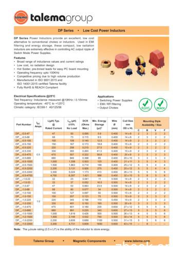
DP Series Power Inductors provide an excellent, low cost alternative to conventional chokes or inductors. Used in EMI filtering and energy storage, these compact, low radiation inductors a


