Case Study No. 4 PEDESTRIAN BRIDGE RÁDLO - Vsb.cz
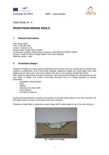
WP6 – Case studies Case study no. 4 PEDESTRIAN BRIDGE RÁDLO 1. General information Date: March 2004 Price: 4 000 000 CZK Investor: Liberec county Design studio: Design office VANER Construction company: Stavby silnic a železnic, ZAKLÁDÁNÍ STAVEB, TESKO Location: Road I/5 close to village Rádlo in the Czech Republic Materials: glulam , steel 2. Investment design Pedestrian bridges are mainly used by pedestrians and cyclists and only occasionally by maintenance vehicles or ambulances. Due to their lower loadings, pedestrian bridges are mostly lighter than road bridges and are often seen to be more suited to the use of a low modulus material like timber. With regard to appearance and also to structure, open and covered bridges are distinguished as two main types of bridge. The choice of the best structural form of a bridge depends on several parameters: - topography and landscape; - span; - loading; - clearance and clear width; - soil conditions; - architectural features. Another principal distinction concerns the position of the deck plate relative to the main structure: the deck plate may be on top or at the base of the main structure. Pedestrian bridge Rádlo is designed as open bridge with the deck plate on top of the main structure. Fig. 1 Model of the bridge 1
WP6 – Case studies 3. Bearing system For the bridge structure itself, a large number of bearing systems are possible to be used. Most bridges consist of one of the following basic forms: beams on two or more supports, trussed systems, kings and queens post trusses, strut frame systems, frame systems, arch systems, suspended and cable-stayed systems, chainlike structure. Pedestrian bridge Rádlo is designed as chainlike structure. 4. Computational models used The simplified models and methods were used. The simplified method was based on an equivalent constant amplitude fatigue loading, representing the fatigue effects of the full spectrum of loading events. The stress was determined by an elastic analysis under the specified action. The fatigue loading from traffic was obtained from the project specification in conjunction with EN 1991-2. The number of constant amplitude stress cycles per year was taken from EN 1991-2. 5. Actions on structures The design of bridge was in accordance with EN 1990. Actions used in design of bridge were obtained from the relevant parts of EN 1991: EN 1991-1-1 Densities, self-weight and imposed loads EN 1991-1-3 Snow loads EN 1991-1-4 Wind loads EN 1991-1-5 Thermal actions EN 1991-1-6 Actions during execution EN 1991-1-7 Accidental actions due to impact and explosions EN 1991-2 Traffic loads on bridges. Variable actions due to the passage of vehicular and pedestrian traffic were regarded as short-term actions. 6. Project documentation, plans, and drawings Fig.2 View of the bridge
WP6 – Case studies Fig. 3 Floor plan of the bridge Fig. 4 Cross section of the bridge 7. Erection The final phases in the provision of a timber bridge are transport and erection. These may appear insignificant in the realisation of a project but they require the same attention as the preceding phases, in that together they can influence not only the design but also the budgeting and the management of the project. Erection represents, in the construction of a timber structure, the moment in which all the previous stages are verified. A well executed assembly is a primary condition to achieve a good building but it is not a sufficient condition. It is necessary that all the previous phases (design, engineering, fabrication, machining and transportation) are correctly executed, to be followed by skilled erection of the structure. Workmen have to be skilled, with experience in timber construction and with complete and efficient tools and machines. The site must be ready for receiving the timber structural elements in order to allow workmen to operate easily and with safety. Erection of a timber structure is usually carried out by placing first the main columns and beams and then the secondary elements. Due to the fact that these frequently have a role in bracing the structure, provisional bracing must be provided. Assembly procedure depends on the type of structural system.
WP6 – Case studies Fig. 5 Bridge erection sequence
WP6 – Case studies 8. Interesting construction details The reason for decay in timber bridges is nearly always poor detailing for durability and neglected maintenance. All aspects of timber protection and maintenance should therefore be considered even during the planning phase of bridge. Timber as a natural product is part of a life cycle of growing and decomposition. One method to break this cycle and hence preserve the timber is to keep the wood material constantly dry. This is a very effective method to preserve the load carrying capacity and the functioning of the bridge during its planned life time. This goal can be achieved using a timber protection plan relating to the elements shown in Tab. 1. Element Conceptional design Choice of material Design of details Preservative treatment Surface treatment Objective Prevention or decrease of intense weather exposure Prevention of damage through adequate choice of materials Prevent unfavourable consequences of shrinkage and swelling due to water contact Prevention of fungi or insect attack Prevent weathering of surfaces, achieve dimensional stability and avoid cracks; limited protection against fungi or insect attack Measure Roof or covering of the main structure Use of either naturally durable or preservatively treated timbers; low moisture content during erection Covering of horizontal surfaces, of joints and of end grain; enable quick drying out of wet parts Pressure treatment using chemical solutions Several layers of pigmented coating Tab. 1 Timber protection plan 9. Protection from weather effects The deck protects the main structure from moisture and mechanical damage from traffic. Apart from the timber members the metal fasteners and fittings have to be protected against corrosion. Especially from the use of salt to keep the roads free from ice and snow in the winter and the use of salts for treating the timber which leads to accelerated corrosion of steel parts. Because fasteners in timber connections are not accessible after erection of the structure, they have to be protected permanently. Hot-dip galvanizing and eventually additional layers of protective coating lead to a prolonged lifetime of fasteners and metal fittings. In more aggressive environments stainless steel is preferred. 10. Economical and ecological aspects During recent years a real renaissance of timber bridges has taken place. One reason is the increasing interest in using such a durable and ecologically sound building material as timber. Apart from that, technological developments have contributed to new and more efficient jointing techniques and the use of wood-based materials. Timber bridges are thus shown to be effective, economic and durable and to allow innovative and aesthetic solutions. Instructions and case study no X were prepared by Petr Kuklík.
The design of bridge was in accordance with EN 1990. Actions used in design of bridge were obtained from the relevant parts of EN 1991: EN 1991-1-1 Densities, self-weight and imposed loads EN 1991-1-3 Snow loads EN 1991-1-4 Wind loads EN 1991-1-5 Thermal actions EN 1991-1-6 Actions during execution
series b, 580c. case farm tractor manuals - tractor repair, service and case 530 ck backhoe & loader only case 530 ck, case 530 forklift attachment only, const king case 531 ag case 535 ag case 540 case 540 ag case 540, 540c ag case 540c ag case 541 case 541 ag case 541c ag case 545 ag case 570 case 570 ag case 570 agas, case
Bicycle and Pedestrian Design Guide. Where there is a discrepancy between content in this Part 800 and the Oregon Bicycle and Pedestrian Design Guide, this Part 800 takes precedence. The Oregon Bicycle and Pedestrian Design Guide is for use by local agencies to develop their standard of practice for the bicycle and pedestrian realms.
rural pedestrian fatalities in these states were clear weather, hours of darkness, weekends, non-intersection locations, and level, straight roads. The project also examined all rural pedestrian accidents . Though the study was strong restricted /strong to Interstate highways, the characteristics of pedestrian fatalities it identified may resemble
the context of shopping malls and pedestrian malls is examined. The main concern is rooted in the socio-spatial relationship between indoor and outdoor space. Pedestrian malls and shopping malls are analyzed as the formations that create link between the interior and exterior spaces throughout the study, because integrated pedestrian
Case Studies Case Study 1: Leadership Council on Cultural Diversity 19 Case Study 2: Department of the Prime Minister and Cabinet 20 Case Study 3: Law firms 21 Case Study 4: Deloitte Case Study 5: Department of Foreign Affairs and Trade 23 Case Study 6: Commonwealth Bank of Australia 25 Case Study 7: The University of Sydney 26 Case Study 8 .
Thursday, October 4, 2018 Materials Selection 2 Mechanical Properties Case Studies Case Study 1: The Lightest STIFF Beam Case Study 2: The Lightest STIFF Tie-Rod Case Study 3: The Lightest STIFF Panel Case Study 4: Materials for Oars Case Study 5: Materials for CHEAP and Slender Oars Case Study 6: The Lightest STRONG Tie-Rod Case Study 7: The Lightest STRONG Beam
3 Contents List of acronyms 4 Executive Summary 6 1 Introduction 16 2 Methodology 18 3 Case Studies 25 Case Study A 26 Case Study B 32 Case Study C 39 Case Study D 47 Case Study E 53 Case Study F 59 Case Study G 66 Case Study H 73 4 Findings 81 Appendix A - Literature findings 101 Appendix B - CBA framework 127 Appendix C - Stakeholder interview questionnaire 133
signs), and TURNING TRAFFIC MUST YIELD TO PEDESTRIANS signs R10-15. 11.3 Pedestrian Signals Extensive guidance and standards for pedestrian signal warrants are provided in the MD-MUTCD, and are not duplicated in this Chapter. Pedestrian signals must be designed to meet SHA’s current Accessibility Policy & Guidelines for


