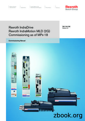
Rexroth Indradrive M Drive Controllers Power Sections-PDF Free Download
Mi, IndraDrive M / IndraDrive ML / IndraDrive C with control sections of the Cxx02 type, – is addressed to persons who mount, operate and maintain IndraDrive Cs, IndraDrive Mi, IndraDrive M / IndraDrive ML / IndraDrive C with control sections of the Cxx02 type
Rexroth IndraDrive M Drive Controllers Power Sections HMx Project Planning Manual DOK-INDRV*-HMS HMD****-PRxx-EN-P Rexroth IndraDrive C Drive Controllers Power Sections HCS02.1 Project Planning Manual DOK-INDRV*-HCS02.1****-PRxx-EN-P Rexroth IndraDrive C Drive Controllers Power Sectio
Rexroth IndraDrive Integrated Safety Technology as of MPx-1x (Safe Motion) Application Manual DOK-INDRV*-SI3*SMO-VRS-APxx-EN-P 338920 Rexroth IndraDrive Rexroth IndraMotion MLD (2G) Libraries as of MPx-18 Reference Book DOK-INDRV*-MLD-SYSLIB3-RExx-EN-P 338916 Rexroth IndraDrive 2)Rexroth IndraMotion MLD (2G) as of MPx-18
Rexroth IndraDrive Drive Controllers Control Sections Project Planning Manual DOK-INDRV*-CSH*****-PRxx-EN-P Rexroth IndraDrive M Drive Controllers Power Sections Project Planning Manual DOK-INDRV*-HMS HMD****-PRxx-EN-P Rexroth IndraDrive C Drive Controllers Power Sections HCS02.1 Project Planning Manual DOK-
Rexroth IndraDrive Drive Controllers Power Sections HCS01 Bosch Rexroth AG I/25 Table of Contents Bosch Rexroth AG DOK-INDRV*-HCS01*UL***-IB06-EN-P Rexroth IndraDrive Drive Controllers Power Sections HCS01 II/25 1 Important Notes
Take the content of the Project Planning Manual "Rexroth IndraDrive Drive System" (DOK-INDRV*-SYSTEM*****-PRxx-EN-P; part no. R911309636) into account. For complete project planning of a Rexroth IndraDrive drive system you need, in any case, the Project Planning Manual "Rexroth IndraDrive Drive
Rexroth IndraDrive Rexroth IndraMotion MLD (2G) as of MPx-18 Application Manual Edition 02 R911338914 LSA Control S.L. www.lsa-control.com comercial@lsa-control.com ( 34) 960 62 43 01 . Rexroth IndraDrive Rexroth IndraMotion MLD (2G) as of MPx-18 Application Manual DOK-INDRV*-MLD3-**VRS*-AP02-EN-P
Power units IndraDrive C and M Rexroth drive system IndraDrive 13 71511 EN/2013-12, Bosch Rexroth AG IndraDrive C – compact converters Power range from 1.5 kW to 630 kW with maximum current from 12 A to 1,535 A High overload capacity Compact design for single-axis appli
Rexroth IndraDrive M Introduction 1-1 DOK-INDRV*-HMS HMD****-PR04-EN-P 1 Introduction 1.1 Documentation Purpose of Documentation This documentation basically contains the technical data of the Rexroth IndraDrive M drive controllers. WARNING Personal injury and property damage caused by incorrect project planning for applications, machines and .
IndraDrive from Rexroth More complete, more intelligent, greater safety With the IndraDrive generation of drives, Rexroth sets yet anot-her milestone in the development of modern automation components for more flexibility, productivity and precision IndraDrive is the application-optimized
Rexroth IndraDrive C Drive Controllers HCS02.1, HCS03.1 R911314905 Edition 01 Operating Instructions Electric Drives and Controls Pneumatics Service Linear Motion and Hydraulics Assembly Technologies. About this Documentation Rexroth IndraDrive DOK-INDRV
Rexroth IndraDrive Mi Drive Systems with KCU02 KSM02, KMS02/03, KMV03, KNK03 Project Planning Manual R911335703 Edition 03 LSA Control S.L. www.lsa-control.com comercial@lsa-control.com ( 34) 960 62 43 01 . Rexroth IndraDrive Mi Drive Systems with KCU02 KSM02, KMS02/03, KMV03, KNK03
Rexroth IndraDrive Drive Controllers Power Sections HCS01 Bosch Rexroth AG I/85. Deutsch English Français Unsachgemäße Handhabung bei Transport und Montage! Verletzungsgefahr! Verwenden Sie geei
Rexroth IndraDrive Drive Controllers - Control Sections CSB01, CSH01, CDB01 Bosch Rexroth AG I/195 Table of Contents Courtesy of CMA/Flodyne/Hydradyne @ Motion Control @ Hydraulic @ Pneumatic @ Electrical @ Mechanical @ (800) 426-5480 @ www.cmafh.com. Page
With the new, compact IndraDrive Cs drive system, Rexroth is expanding the lower power range of the IndraDrive drive platform that has enjoyed worldwide success. In addition to its space-saving design and outstanding performance data the IndraDrive Cs also offers an extensive range of Ether-net-based communic
Rexroth IndraDrive Mi Electronic Control System KCU01 R911339082 Edition 01 Courtesy of CMA/Flodyne/Hydradyne @ Motion Control @ Hydraulic @ Pneumatic @ Electrical @ Mechanical @ (800) 426-5480 @ www.cmafh.com. Rexroth IndraDrive Mi Electronic Control System KCU01 Operating Instructions
Surfaces chaudes ( 60 C)! Risque de brûlure ! Évitez de toucher des surfaces métalliques (p. ex. dissipateurs thermiques). Respectez le délai de refroidissement des composants d'entraînement (au moins 15 minutes). DOK-INDRV*-FCS01*****-IT01-EN-P Rexroth IndraDrive Fc Drive Controllers Frequency Converters FCS01 Bosch Rexroth AG I/69
Drive expertise Rexroth drive system IndraDrive 5 Bosch Rexroth AG, 71 511 EN/2012-11 Safety on Board Safety technology certified to EN 13849-1 Cat. 3 PL d
Rexroth IndraDrive Drive Controllers Power Sections HMD01 R911319995 Edition 06 Courtesy of CMA/Flodyne/Hydradyne @ Motion Control @ Hydraulic @ Pneumatic @ Electrical @ Mechanical @ (800) 426-5480 @ www.cmafh.com
Rexroth IndraDrive C Drive Controllers Power Sections HCS02.1 R911306138 Edition 02 Project Planning Manual . Troubleshooting Guide DOK-INDRV*-GEN-**VRS**-WAxx-EN-P Rexroth IndraDyn S Synchronous Motors MSK Project Planning Manual DOK-MOTOR*-MSK*****-PRxx-EN-P Rexroth IndraDyn A
Rexroth IndraDrive Rexroth IndraMotion MLD (2G) as of MPx-18 Application Manual R911338914 Edition 03
Bosch Rexroth AG Electric Drives and Controls Electric Drives and Controls Bosch Rexroth AG Converters IndraDrive C n HCS03 Electric Drives and Controls, PDF version, as of 2010-03-26, Bosch Rexroth AG, subject to change HCS03.1E-W0070 HCS03.1E-W0100 HCS03.1E-W0150 HCS03.1E-W0210 Dimen
Bosch Rexroth AG Electric Drives and Controls Electric Drives and Controls Bosch Rexroth AG Converters IndraDrive C n HCS02 Electric Drives and Controls, PDF version, as of 2010-03-29, Bosch Rexroth AG, subject to change HCS02.1E-W0012 HCS02.1E-W0028 HCS02.1E-W0054 HCS02.1E-W0070 Dime
Sytronix Solutions with IndraDrive on Press Brakes Technical Information 5/8 RE 08100-01, Edition: 2014-12, Bosch Rexroth G Parameterization of the IndraDrive Control Unit Press brakes often have a main controller (Cybelec, Delem, etc.) which outputs analogue set point values
Renault and Bosch Rexroth Approval signatures on file at Renault. Document Management Information File: Renault Reference Frame Version V3.0 Page 2 of 32 . Drives IndraDrive IndraDrive M, IndraDrive C with Sercos I/O devices Inline /Fieldline Inline, Iumberg IP67 Lion Li
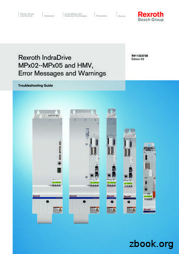
Rexroth IndraDrive MPx02--MPx05 and HMV, Error Messages and Warnings Troubleshooting Guide DOK-INDRV*-GEN*
Rexroth IndraDrive Integrated Safety Technology "Safe Torque Off" (as of MPx-16) Application Manual R911332634 Edition 07 LSA Control S.L. www.lsa
Rexroth IndraDrive Integrated Safety Technology Functional and Application Description DOK-INDRV*-SI*-**VRS**-FK06-EN-P RS-07c04c59dc26fa640a6846a000d3e727-3-en-US-6
MLD-M Sercos master with integrated multi-axis Motion Logic Control functions: More options for each application IndraDrive Mi also sets the course for controllers for advancing to Industry 4.0: With IndraMotion MLD, Rexroth's
Bosch Rexroth AG ServoDyn D 1070066030 / 06 Rexroth ServoDyn D Connectivity Manual Mounting guidelines DOK-SERV*D-IF*MANUAL**-MA06-EN-P The present manual provides information on the installation of the ServoDyn D drive modules. Description Release Date Notes DOK-SERV*D-IF*MANUAL**-MA06-EN-P 08.2004 E Bosch Rexroth AG, 1995 Π2004
the Rexroth IndraDrive family offer flexible solutions with intelligent functions for powerful drive solutions that extend into the megawatt range. 3 Application-specific, modular machines are the key objec-tive, and optimized drive technologies are the way to ach
Bosch Rexroth Bosch Rexroth Korea Ltd. Bosch Rexroth (India) Limited Shanghai Bosch Rexroth Hydraulics & Automation Ltd. 5-1 Higashi-Nakanuki-machi 29 Mieum Sandan 1Ro Gangseo-gu 18/4 -19/4 - Hadapsar Industrial Estate 333 Fuquan (N.) Road Tsuchiura Busan-si Pune Shanghai 300-8588 618-260 411 013 200335 Ibaraki - Maharashtra Shanghai Korea .
Rexroth Frequency Converter Fv R912004885 Edition 03. Bosch Rexroth AG Record of Revision . ①: Refer to "9.3: Derating of Electrical Data" in the Instruction Manual. Tab. 1-1: Ambient conditions Bosch Rexroth AG Mechanical Installation . 2.1.2 Connecting to the Motor Fv Model Output Side International without USA/Canada USA/Canada Cable .
Firmware IndraDrive ADVANCED with MA Option R911328747 FWA-INDRV*-MPH-07VRS-D5-1-ALL-ML Firmware IndraDrive ADVANCED with MA Option R911328736 FWA-INDRV*-MPB-07VRS-D5-1-NNN-TF Firmware IndraDrive BASIC with TF Option R911328707 FWS-MLDTFA-RFS-05VRS-D0 Rollfeed Stand
2 Bosch Rexroth AG Electric Drives and Controls Modular system Power supply units n IndraDrive M - HMV Electri
4 Bosch Rexroth AG IndraDrive Cs for Linear Motion Systems R310EN 2735 (2010.11) Product Description Maintenance-free MSM motors are available in five sizes with continuous mechanical out
IndraDrive servo amplifier in combination with maXYmos NC Type 5847. . The communication between IndraDrive and . Bosch-Rexroth Type 2180A. Standard interface SERCOS III (internal bus) Evaluation unit 3) maXYmos NC Type 5847. Standard interface PROFIBUS, PROFINE
DOK-INDRV*-AXCOUPVRS**-AP01-EN-P Bosch Rexroth AG 5/49 IndraDrive Axis Linking Functions Introduction The different types of linking make varying demands on the encoder system. For torque linking and velocity linking, a single-turn encoder at the slave axis is sufficient. For position linking, however, an absolute
Rexroth IndraDrive Supply Units, Power Sections HMV, HMS, HMD, HCS02, HCS03 Power sections for converters - IndraDrive C. Power dissipation, mounting position, cooling, distances Description SymbolCooling and power dissipation dataUnit HCS03.1 E-W0070-_-05 HCS03.1 E-W0100-_-05 HCS03.1 E-W0150-_-05 HCS03.1 E-W0210-_-05 HCS03.1 E-W0280-
DKR02, DKR03 and DKR04 Drive Controllers Project Planning Manual DOK-DIAX03-DKR*****-PR02-EN-P mannesmann Rexroth engineering Indramat Rexroth SYSTEM200


