Rotor Dynamic Analysis Of Centrifugal Compresser Due To-PDF Free Download
flapping trimmed to near zero. The new RTA rotor balance provides increased accuracy in measuring rotor hub loads. This five- component rotor balance measures rotor lift, drag and side forces, together with the rotor pitching and rolling moments. Also incorporated was an instrumented flex coupling to measure rotor torque.
ROTOR DYNAMIC ANALYSIS OF STEAM TURBINE ROTOR USING ANSYS Nagaraju Tenali 1* and Srinivas Kadivendi *Corresponding Author: Nagaraju Tenali, tenali.n1830@gmail.com Rotor dynamics is a field under mechanics. Mainly deals with the vibration of rotating structures. In recent days, the study abo
Salient pole rotor - the individual rotor poles protrude from the center of the rotor, characterized by concentrated windings, non-uniform air gap, larger rotor diameters, used in applications requiring low machine speed and a large number of machine poles (example - hydroelectric generation). 2. Cylindrical rotor - the individual rotor poles .
rotor has been designed and analyzed by using the guidelines as per API 610 standards. Keywords: Resonance, Modal analysis, Vibration, Rotor dynamics, Centrifugal pump, FEM, API. I. INTRODUCTION A centrifugal pump converts the input power to kinetic
525.9835Hz, then using Ansys software to carry out modal analysis under different constraint conditions on the screw rotor, the modal that the screw rotor, the finite element . frequency using the dunkery calculation method of screw rotor. The screw rotor shaft is simplified as uniform, equivalent diameter d by type (1) to calculate 36.6mm, d i
This study deals with the design and performance analysis of centrifugal pump impeller. In this thesis, centrifugal pump is analyzed by using a single-stage end suction centrifugal pump. Two main components of a centrifugal pump are the impeller and the casing. The impeller is a rotating component and the casing is a stationary component.
Centrifugal compressor ၌ peripheral velocity rotating speed (from 1800 to 50,000 rpm) Centrifugal chiller ၏ refrigeration capacity 100 tons (350 kW) 10,000 tons(35,000 kW) centrifugal chiller Centrifugal chiller turbo machine positive .
The main rotor system includes the main rotor blades, the main rotor head, the rotating controls, the main rotor indicating system. The main rotor blades are of composite material. Each blade consists of: – A fiberglass spar – A trailing edge made of a graphite-fiber skin and a Nomex core
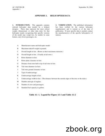
A Manufacturer name and helicopter model B Maximum takeoff weight in pounds. C Overall length in feet. (Rotors at their maximum extension.) D Overall height in feet. (Usually at tail rotor.) E Rotor diameter in feet. F Rotor plane clearance in feet. G Distance from rotor hub to tip of tail rotor
TELC maximum power ratings are based on winding temeprature rise of 130 C. Consult factory for performance using special rotor. 3. MAXIMUM SPEED: For standard rotor, this is the maximum allowable speed using die-cast rotor construction and standard rotor bores. For special rotor, thi
Proceedings of ASME Turbo Expo 2016: Turbomachinery Technical Conference and Exposition GT2016 June 13 – 17, 2016, Seoul, South Korea GT2016-56392 EFFECT OF AFT ROTOR ON THE INTER-ROTOR FLOW OF AN OPEN ROTOR PROPULSION SYSTEM Paul E. Slaboch Saint Martin’s University Lacey, WA, USA David B. Stephens and Dale E. Van Zante
trunnion to minimize rotor flapping. Blade pitch is altered by movement of the tail rotor control pedals to control or maintain heading. This blade pitch change provides anti-torque control. Power to drive the tail rotor is supplied from a take-off on the lower aft section of the main rotor transmission. TAIL ROTOR BLADES
TEST COMPRESSOR AND EXPERIMENTAL MEASUREMENTS A low aspect ratio transonic inlet rotor for a core compressor, des-ignated NASA rotor 37, was used for the present study. The rotor was originally designed and tested at NASA Lewis Research Center in the late 1970's by Reid and Moore [14 and 15]. The rotor has a design
- a short-circuit rotor, more commonly defined squirrel-cage rotor. The main difference between these two types derives from the structure of the rotor. More precisely, the first type of rotor is constituted by real windings as those of the stator, it presents a more complex and fragile structure (brushes sliding on the rotor, with the possible
helicopter (including fuselage and tail rotor) with rotor blades 8.98 feet in diameter. The blades were dynamically scaled and had representative coning angles, with a slightly larger blade solidity of 0.08504 compared to 0.0826 of the standard rotor. Hover testing was conducted both with and without the fuselage to measure isolated hover .
Solid model rotor dynamics is a method of performing the rotor dynamics analysis by solid elements instead of the conventional beam models. Therefore, in the product development process, there is no change in the stage at which it occurs. As rotor dynamic analyses are system
PERFORMANCE ANALYSIS OF CENTRIFUGAL PUMP OPERATING AS TURBINE FOR IDENTIFIED MICRO/PICO . Complete and segment 3D CFD fluid domain of centrifugal pump impeller model. Fig.3: 3D model of a centrifugal pump volute fluid volume. . it can be seen that to make the flow through PAT more realistic, the f
Vibration Analysis of Centrifugal Pump by Nurulhusna binti Mohd Mohtar . energy to a fluid through centrifugal force. 5 Figure 2.1.1: General components of a centrifugal pump. (Sandev) . By creating a resistance to the
Experimental Dynamic Analysis of a Breathing Cracked Rotor . steam and gas turbines, generators, and pumps [12–14]. Fatigue cracking of rotor shafts is an important phe-nomenon that can lead to severe damage and great eco-nomi
Ultra Centrifugal Mill ZM 200 The powerful drive of the innovative Ultra Centrifugal Mill ZM 200 ensures rapid grinding results. Together with its extremely efficient operation the ZM 200 can prepare 100 samples or more per day for analysis. More on page 4. 2 ROTOR MILLS
helicopter main rotor or rotor system is the combination of several rotary wings (rotor blades) and a control system that generates the aerodynamic lift force that supports the weight of the helicopter, and the thrust that counteracts aerodynamic drag in forward flight.
Dec 06, 2018 · Dynamic Strategy, Dynamic Structure A Systematic Approach to Business Architecture “Dynamic Strategy, . Michael Porter dynamic capabilities vs. static capabilities David Teece “Dynamic Strategy, Dynamic Structure .
Carrier has led the development of centrifugal chiller, including the invention of centrifugal chiller in 1922, manufacture of the first centrifugal chiller with cooling capacity of 10,000 RT in 1972, and introduction of non-ozone-depleting, chlorine-free refrigerant HFC-134a in 1996. Model Number Nomenclature Cooling Capacity Features .
The pump is a centrifugal, single stage close-coupled type. When properly installed and when given reasonable care and maintenance, centrifugal pumps should operate satisfactorily for a long period of time. Centrifugal pumps use the centrifugal force principal of accelerating the liquid within a rotating
THE MUST-HAVE HANDBOOK FOR CENTRIFUGAL PUMPS Page 3 An overview of centrifugal pumps. Centrifugal pumps are a very broad category of pumps. They vary so much in size, capacity, and abilities that it can be difficult to understand which is right for your ap-plication. This guide is design
Rod Machado’s Private Pilot Handbook B18 HOW CENTRIFUGAL FORCE CAUSES YOU AND THE AIRPLANE TO FEEL HEAVIER IN A TURN MEFLI2 Centrifugal Force Resultant orce Gravity Resultant orce Centrifugal MEFLI2 Force Centrifugal Force Gravity During a sharp turn on a level road, you feel a newly generated force known as
Fire water Diesel engine driven extended shaft centrifugal pump Hydraulic motor drive for fire water centrifugal pump Utilities Diesel engine driven alternator . 2.2.2 Electric Motor driven Multi-stage Centrifugal Pump. Page 2.2 - 11 2.2.3 Electric Motor driven Vertical Centrifugal Pump.Page 2.2 - 18 .
Centrifugal Pump - 5 day programme on Toplink Engineers from BP, Kuala Lumpur March Best Practices Centrifugal Pumps and Shell, Power Companies 2012 Mechanical Seals & Water Utilities 18. PUMPSCHOOL Design & Application of Delivered jointly with Company Training of Melbourne May 2012 Centrifugal Pumps Australian Industrial design & Applications
Centrifugal pump 2 A centrifugal pump uses a spinning "impeller," which normally has backward-swept blades that directly push water outward. To arrive by a simpler method than that just given at a general idea of the mode of action of the exterior whirlpool in improving the efficiency of the centrifugal pump, it is only necessary to
Centrifugal Pump Curves. Summary. Reading and understanding centrifugal pump curves is key to proper pump selection, and to their reliable and efficient operation. This . Tech Brief. examines how pump curves can provide data about a pump's abili ty to produce flow against certain head, shows how to read a typical centrifugal pump curve, and .
Models of centrifugal pump with three different grid numbers are simulated at design flow rate, and the pump heads are obtained, as Fig. 1. Physical model of centrifugal pump with high specific speed. Table 1 Main parameters of centrifugal pump. 95 143 24 23 Suction Impeller Outlet Inlet diameter diameter width blade angle D j/mm D 2/mm b 2 .
Centrifugal Mud Pump (Equivalent to NOV Mission Magnum series) BETTER's Centrifugal Mud Pumps as proven delivers reliable performance, better longevity, and cost savings compared to other centrifugal mud pumps made in China. Size ranges from 3x2x13; 4x3x13; 5x4x14; 6x5x11; 6x5x14; 8x6x11; 8x6x14; 10x8x14 to 14x12x22. .
Paper 1. Assessment of the 3D Flow in a Centrifugal compressor using Steady-State and Unsteady Flow Solvers 91 Paper 2. Generation Mechanisms of Rotating Stall and Surge in Centrifugal Compressors 117 Paper 3. Centrifugal Compressor: The Sound of Surge 137 Paper 4. Acoustic signature of flow instabilities in radial compressors 163 Paper 5.
Centrifugal Pipe K 2 L Centrifugal Pipe Fittings M S Centrifugal Pipe Fittings *2", 2 1 / 4 " and 3" sizes of pipe are no longer manufactured by AMERICAN and dimensions are given for information only. 2" and 2 1 / 4 " sizes are not shown in AWWA C111. **14"-48" Mechanical Joints are not available on centrifugal pipe.
MAGNETIC BEARING CENTRIFUGAL CHILLER WITH OPTIVIEW CONTROL CENTER CENTRIFUGAL LIQUID CHILLERS WITH R-1233zd REFRIGERANT OPERATIONS AND MAINTENANCE NEW RELEASE Form 161.01-OM1 (618) . The YORK Model YZ Centrifugal Chiller is complete - ly factory-packaged. The package includes the evapo-rator, condenser, compressor, motor, variable speed
Ultra Centrifugal Mill ZM 200 General Information The Ultra Centrifugal Mill ZM 200 is a high speed rotor mill with unmatched performance. It is used for the rapid size reduction of soft to medium-hard and fibrous materials. Because of the efficient size reduction technique the ZM 200 ensures the gentle
various Short Courses on testing of centrifugal compressors. Mr. Colby presently is a Test Engineering Supervisor developing test methods to meet objectives for production compressors and analytical aerodynamic testing of centrifugal Dr. Edmund A. Memmott is a Principal Rotor Dynamics Engineer at Dresser-Rand.
a centrifugal compressor, a range of approximately 0.1 to 0.12 is optimum(2). Nn G S ad y / / / r f pm 01 h 34 34. (6) Here, n represents the rotor speed of a compressor. Originally, the specific speed is a dimensionless number for evaluating how much the rotation number falls outside the optimum range. In the case of a centrifugal .
Argos Technologies Flexifuge Mini Centrifuge — Operator’s Manual English Specifications Speed Slow: 6,000 RPM Fast: 9,200 RPM Relative Centrifugal Force 6000rpm 9200rpm 1.5ml Rotor 2012G 4731G 0.2ml PCR Strip 1509G 3549G 5ml Rotor 2414G 5677G Noise Level 65dB Rotor Capacity C
Starting of 3-Phase Induction Motors The induction motor is fundamentally a transformer in which the stator is the primary and the rotor is short-circuited secondary. At starting, the voltage induced in the induction motor rotor is maximum (Q s 1). Since the rotor impedance is low, the rotor current is excessively large.


