Steering Intermediate Shaft Noise Australiancar Reviews-PDF Free Download
442 steering gear 443 steering gear, power steering 444 tie rod 445 tie rod without end (axial joint) 446 tie rod end 447 protection boot/sleeve 448 rubber mount for steering gear 449 joint shaft 450 steering damper 451 power steering pump 452 oil tank for power steering 455 steering wheel 456 steering column and parts
creating a solid shaft from the box to the steering wheel. The steering column shaft is a unique item. It tapers down from 3/4” diameter inside the column to the 5/8” before entering the coupler. Like the steering box input shaft, the column shaft is fully splined at the tip. This me
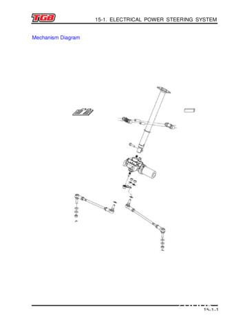
90 , the power steering will back to normal and steering assist should resume normal operation. 15-1. ELECTRICAL POWER STEERING SYSTEM 15-1-4 Steering Torque Sensor The steering column is connected to the shaft on the EPS unit. A small area of the EPS shaft is magnetized. Inside the EPS u
The splines of the transmission output shaft or transfer case input shaft may be worn (rusted) or the shaft may have broke. The splines of the transmission output shaft have been updated with a grove for a O -Ring to help maintain the grease located between the transfer case input shaft and the transmission output shaft. Updated shafts require that “both the output shaft and input shaft be .
Manual transmission/transaxle - Manual transmission ASSY MT-2 MT MT-02918 Non-reusable parts MG GEAR OIL SPECIAL II Gear shift fork No. 2 Shaft snap ring Straight pin Shaft snap ring Output shaft Gear shift fork No. 3 Gear shift fork No. 1 Shaft snap ring Shaft snap ring Shaft snap ring 19.5 {198.8}{14.4} Counter shaft Gear shift fork shaft No. 1
Visually inspect for irregularities in the shaft seal or an uneven alignment where the shaft seal contacts the motor. . VPH-SST-Fxxx Shaft Seal Back View of Shaft Seal (motor facing) Inside of Shaft Seal Lip VPS-SST-xxxx Shaft Seal MPS-SST-xxxx Shaft Seal. Rockwell Automation Publication 2090-IN012E-EN-P - February 2019 5
Noise Figure Overview of Noise Measurement Methods 4 White Paper Noise Measurements The noise contribution from circuit elements is usually defined in terms of noise figure, noise factor or noise temperature. These are terms that quantify the amount of noise that a circuit element adds to a signal.
Abstract - In present the car steering system used by us is 2 wheel steering system and in standard 2 wheel steering the rear wheel set is idle and not to play a role in steering. While in 4 wheel steering system the rear and front both wheels are active and can guide in steering. Here we using MARUTI-800 car as a reference model.
Abstract - In present the car steering system used by us is 2 wheel steering system and in standard 2 wheel steering the rear wheel set is idle and not to play a role in steering. While in 4 wheel steering system the rear and front both wheels are active and can guide in steering. Here we using MARUTI-800 car as a reference model.
A motor-driven power steering apparatus comprising a steering assisting motor, a torque sensor detecting steer ing torque, a vehicle speed sensor, and a steering angu lar velocity detecting unit detecting steering angular velocity of steering mechanism. The power steering apparatus sets the value of current to be delivered to the steering .
13. zfls 8018 power steering with steering input 12" forward 14. trw power steering pump 15. 1.6 quart power steering reservoir 16. steering shaft with joint boot 17. steering column floor mount boot front suspension 1. 16,000# zf rl80em independent front air suspension 2. sachs front shock absorbers 3. single front air suspension leveling valve
2 160-00682 Steering wheel 3 160-00683 Steering wheel cover 4 104-00002 ZENN steering wheel logo 5 160-00511 Lock barrel ignition/door(Ignition 2 door lock cylinder and 2 keys) 6 160-00097 Steering shaft 7 160-00142 Steering tie rod washer (inner tie rod) 8 160-00258 Steering ball tie rod end (Outer tie rod) 9 160-00259 Rack & pinion boot
Gearbox Application Bearing (Designation) 11 DAF ZF 16S-160 / 160 / 1 Input shaft VKT 8899 BC1B 322161 Counter shaft, front VKT 8886 331305 A/Q Counter shaft, rear VKT 8897 5395/5335 Planet carrier, centre VKT 8942 61916 Output shaft VKT 8940 6218/C3 ZF 16S-181 Input shaft VKT 8490 30217 J2/QVB478/30217/QVB016 8) Main shaft, front VKT 8956 4395/2/QCL7CVQ492 Counter shaft, front VKT 8897 5395/5335
new! 0.5 769910 drive shaft & splines remove broken upper mercruiser new! 3.6 769500 drive shaft coupler r&r 4.5 577060 drive shaft housing r&r 3.8 704160 drive shaft housing r&r ob 35-50hp 4.5 744200 drive shaft housing reseal io 1.5 757820 drive shaft seal r&r w/full drive service new! 1.0 769490 drive shaft strut r&r dynos 0.9 578100 dyno .
Replacement Spare Parts for CATERPILLAR Tractor Automobile Spares Italy 4E2134 GEAR-SUN 4E5322 COLLAR 4E9426 COLLAR 8E6258 PIN 8E7455 GEAR 8E7456 GEAR 1F4256 SHAFT-TRACK 1F7797 GEAR 1F8750 GEAR 2F2004 CAP A. 2F2992 GEAR 2F6869 PIN 2F7479 SHAFT 2F7507 SHAFT-TRACK 2F7520 SHAFT 2F7576 SHAFT-TRACK 2F7577 SHAFT-TRACK 2F7993 SHAFT A. 3F1518 U-JOINT .
The Noise Element of a General Plan is a tool for including noise control in the planning process in order to maintain compatible land use with environmental noise levels. This Noise Element identifies noise sensitive land uses and noise sources, and defines areas of noise impact for the purpose of
7 LNA Metrics: Noise Figure Noise factor is defined by the ratio of output SNR and input SNR. Noise figure is the dB form of noise factor. Noise figure shows the degradation of signal's SNR due to the circuits that the signal passes. Noise factor of cascaded system: LNA's noise factor directly appears in the total noise factor of the system.
noise and tire noise. The contribution rate of tire noise is high when the vehicle is running at a constant speed of 50 km/h, reaching 86-100%, indicating tire noise is the main noise source [1]. Therefore, reducing tire noise is important for reducing the overall noise of the vehicle and controlling noise pollution [2].
Figure 1: Power spectral density of white noise overlaid by flicker noise. Figure 2: Flicker noise generated from white noise. 1.1 The nature of flicker noise Looking at processes generating flicker noise in the time domain instead of the frequency domain gives us much more insight into the nature of flicker noise.
2009 – 2010 Corolla, Matrix Introduction Some 2009 – 2010 Corolla and Matrix vehicles may exhibit a clunk, pop, or knocking noise when turning the steering wheel to the left or right. A new intermediate shaft has been developed to address this condition. Use the following repair procedure to remove and replace the steering intermediate shaft.
truck & suv heavy duty steering shafts power steering upgrades muscle car power steering conversions saginaw manual steering boxes p/s pumps, brackets & pulleys street rod universal joints & shafts steering columns & mounts saginaw manual steering boxes
S ELECTRONIC POWER STEERING 2609-002 FLUID LEVEL INDICATOR Elec Power Steering Fluid Level Indicator 1 S POWER STEERING PUMP2603-001 Power Steering Pump TRW 1 O 2606-014 FRONT AXLE CRAMP ANGLE Front Axle Cramp Angle 50L/45R Degrees 1 O 2610-003 POWER STEERING GEAR Power Steering Gear TRW TAS 65 w/Assist 1
the steering wheel. The steering valve will then act as a pump. Steering is heavy to use and it works slowly. At full---lock it is possible to force the steering wheel further. CAUTION: If a malfunction occurs in the steering system the tractor should be stopped and the malfunction corrected before restarting. D 2.2.2. Steering wheel height .
Steering systems are carefully designed so that the driver can, without too much effort, keep the vehicle going straight ahead or turn it to the right . The steering wheel is located at the top of a steering column. As it is turned, a steering gear at the bottom of the column is operated. The steering linkage is all of the levers, rods, arms, .
steering return of a motor driven power steering system , which enables an overshoot - free center stop to be made as well as enables a quick return to be made , when returning after steering by a large steering angle in the motor driven power steering system . . . . . . . . . . 11 Claims , 5 Drawing Sheets START 10 CALCULATE DAMPING FORCE S20
Steering gear box: - fundamentals screw and nut steering gear mechanism-worm and roller type steering gear box - Re-circulating ball nut and rocker lever, re-circulating ball rack and sector steering gear box- need of power assisted steering. External direct coupled and rack and pinion and integrated steering power cylinder, power
the steering rack. This pinion is driven by an electric motor. The motor engages in the steering rack via a worm gear and drive pinion and thereby transmits the force required for steering assistance. 6. The sum of the turning force on the steering wheel and the assisting force is the effective force applied on the steering gear to move the .
0002 The present invention relates to a motor-driven power Steering apparatus for a vehicle. 0003 2. Description of the Related Art 0004. In a motor-driven power steering apparatus for a vehicle, there is a structure made to transmit Steering torque applied to a steering wheel to a pinion shaft of a rack and
steering box and steering shaft. Loosen the steering column brackets so you can pull it back to remove the steering shaft from the coupler. Remove the cou-pler from the gearbox. Take the coupler to the auto parts store, and purchase a rebuild kit that includes new bolts and washers,
the noise figure of the receiver. Noise figure has nothing to do with modulation or demodula-tion. It is independent of the modulation format and of the fidelity of modulators and demodulators. Noise figure is, therefore, a more general concept than noise-quieting used to indicate the sensitivity of FM receivers or BER used in digital .
The Noise figure is the amount of noise power added by the electronic circuitry in the receiver to the thermal noise power from the input of the receiver. The thermal noise at the input to the receiver passes through to the demodulator. This noise is present in the receive channel and cannot be removed. The noise figure of circuits in the .
extract the noise figure of the DUT from the overall system noise measurement. This step is referred to as second-stage noise correction, as the DUT’s mea-sured noise figure is corrected based on the gain and noise figure of a second stage, which in this case is the test instrument’s noise receiver.
A noise factor of 1, no degradation in signal to noise, produces a noise figure of 0 dB. HF receiver noise figures will range from about 10 to 20 dB. VHF and UHF receivers will often exhibit a lower noise figure, 8 to 15 dB, to take advantage of the lower atmospheric noise environment found there. The receiver noise figure is primarily a .
Noise Contours 19 Input Voltage Noise 20 Dynamic Reserve 20 Appendix A Remote Programming A-1 Introduction A-1 Commands A-1 Appendix B Noise Sources and Cures B-1 Intrinsic Noise Sources B-1 Johnson Noise B-1 '1/f' Noise B-1 Others B-1 Non-Essential Noise Sources B-1 Capacitive Coupling B-2 Inductive Coupling B-2
2 Marc Levoy Outline examples of camera sensor noise don’t confuse it with JPEG compression artifacts probability, mean, variance, signal-to-noise ratio (SNR) laundry list of noise sources photon shot noise, dark current, hot pixels, fixed pattern noise, read noise SNR (again), dynamic range (DR), bits per pixel ISO denoising by aligning and averaging multiple shots
antenna system Noise Margin Noise Margin. Noise Level ITU-R P.372-13. Noise Level ITU-R P.372-13 Shows 46 dB noise on 160 at 1Hz bandwidth for a quiet rural receiving site 64dB for a residential area receiving site. Noise Level ITU-R P.372-13 Shows 46 dB noise on 160 at 1Hz
Background noise due to flow in wind tunnels contaminates desired data by decreasing the Signal-to-Noise Ratio. The use of Adaptive Noise Cancellation to remove background noise at measurement microphones is compromised when the reference sensor measures both background and desired noise. The technique proposed modifies the
Tsubaki: The solution for shaft locking devices More information at www.ustsubaki.com Couplings Coupling Installation using AS Series Servo Motor Shaft Ball Screw Shaft POWER-LOCK Servo Motor Shaft Ball Screw Shaft POWER-LOCK Backlash free and highly accurate disc couplings are excellent
pto shaft g283s01-2 mec,indp range gear shaft g285s01-1 hst range gear shaft g285s01-2 mec pto drive shaft g287s01-3 indp,pto1 4wd shaft g288s01-2 4wd,dry,au,eu,usld,usm . 4wd shaft g288s01-3 2wd,lsta . 11 * bushing-camshaft front-egq100 부싱 1 2010-04-14
H: 3 way gearbox, input shaft clockwise rotation direction, left side output shaft clockwise rotation direction, inline output shaft anticlockwise rotation direction. L: 3 way gearbox, input shaft clockwise rotation direction, right side output shaft anticlockwise rotation direction, inline output shaft anticlockwise rotation direction.


