Tk126d Pneumatic Electric Amp Hydraulic Power Tools-PDF Free Download
PSI AP Physics 1 Name_ Multiple Choice 1. Two&sound&sources&S 1∧&S p;Hz&and250&Hz.&Whenwe& esult&is:& (A) great&&&&&(C)&The&same&&&&&
Argilla Almond&David Arrivederci&ragazzi Malle&L. Artemis&Fowl ColferD. Ascoltail&mio&cuore Pitzorno&B. ASSASSINATION Sgardoli&G. Auschwitzero&il&numero&220545 AveyD. di&mare Salgari&E. Avventurain&Egitto Pederiali&G. Avventure&di&storie AA.&VV. Baby&sitter&blues Murail&Marie]Aude Bambini&di&farina FineAnna
The program, which was designed to push sales of Goodyear Aquatred tires, was targeted at sales associates and managers at 900 company-owned stores and service centers, which were divided into two equal groups of nearly identical performance. For every 12 tires they sold, one group received cash rewards and the other received
This combination of basic pneumatic knowledge and practice with hands-on equipment helps learners build the pneumatic skills they will need to succeed in the workplace. 1. Pneumatic Power Systems 2. Basic Pneumatic Circuits 3. Principles of Pneumatic Pressure and Flow 4. Pneumatic Speed Control Circuits 5. Pneumatic DCV Applications Air Logic 7.
Hydraulic radial piston motors Hydraulic axial piston motors Pneumatic motors Pneumatic starters Hydraulic and pneumatic controls Hydraulic power units Designing controls and hydraulic power units specii c to the customer is our company s major strength. Vast product diversity is also available for standardized products.
College"Physics" Student"Solutions"Manual" Chapter"6" " 50" " 728 rev s 728 rpm 1 min 60 s 2 rad 1 rev 76.2 rad s 1 rev 2 rad , π ω π " 6.2 CENTRIPETAL ACCELERATION 18." Verify&that ntrifuge&is&about 0.50&km/s,∧&Earth&in&its& orbit is&about p;linear&speed&of&a .
HYDRAULIC BOTTLE JACKS 1 HYDRAULIC BOTTLE JACKS K12150 - 1850kg Hydraulic Bottle Jack K12151 - 4000kg Hydraulic Bottle Jack K12152 - 6000kg Hydraulic Bottle Jack K12153 - 10000kg Hydraulic Bottle Jack K12157 - 20000kg Hydraulic Bottle Jack K12158 - 10000kg Hydraulic Bottle Jack K12159 - 20000kg Hydraulic Bottle Jack ED1 / JUNE 19 Distributed by Kincrome Tools and Equipment www.kincrome.com.au
Hydraulic and Pneumatic Systems Topic 1.0.0 Hydraulic Systems 2.0.0 Pneumatic Systems Overview In automotive and construction equipment, the terms hydraulic and pneumatic describe a method of transmitting power from one place to another through the use of a liquid or a gas. Certain ph
The construction of pneumatic and hydraulic cylinders is quite similar. The main difference is that a hydraulic cylinder may exert a pressure of, perhaps, 100 bar, whereas a typical pressure exerted by a pneumatic cylinder might be around only 10 bar. Sample Unit WorkBook 2 - Level 4 ENG- U29: Electro, Pneumatic and Hydraulic Systems
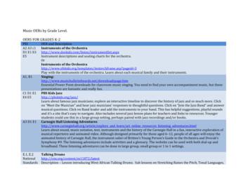
theJazz&Band”∧&answer& musical&questions.&Click&on&Band .
1 Parker Hannifin Corporation Parflex Division FluidConnectors Ravenna, Ohio Coiled Air Hose, Fittings & Accessories Hydraulic & Pneumatic Hose & Fit. PTFE Hose & Fittings Thermoplastic Tubing Truck (Fleet) Products Tooling & Equipment . described in detail within this catalog. We urge you to review this section before you proceed with
All main pneumatic components can be represented by simple pneumatic symbols. Each symbol shows only the function of the component it represents, but not its structure. Pneumatic symbols can be combined to form pneumatic diagrams. A pneumatic diagram describes the relations between each pneumat
6" syl 4" syl 12" swgl @ 45 & 5' o.c. 12" swchl 6" swl r1-1 ma-d1-6a 4" syl 4" syl 2' 2' r3-5r r4-7 r&d 14.7' 13' cw open w11-15 w16-9p ma-d1-7d 12' 2' w4-3 moonwalks abb r&d r&d r&d r&d r&d r&d ret ret r&d r&d r&d r&d r&d 12' 24' r&d ma-d1-7a ma-d1-7b ret r&d r&d r5-1 r3-2 r&d r&r(b.o.) r6-1r r3-2 m4-5 m1-1 (i-195) m1-1 (i-495) m6-2l om1-1 .
Unit: D6 Hydraulic and Pneumatic Power Control Systems Level: Four Duration: 7 hours Theory: 3 hours Practical: 4 hours Overview: This unit is designed to provide the apprentice with the knowledge about hydraulic and pneumatic power control systems. This unit covers hydraulic and pneumatic devices, and the use and applications of hydraulic and
compressor pneumatic cylinder, pneumatic cylinder, piston pump. The aim of the project is pneumatic operated piston water pump. The piston is reciprocated with the help of a pneumatic cylinder solenoid valve. There are two cylinders are used in this project, one for pneumatic cylinder and another one for hydraulic cylinder.
S0932.9 Hydraulic Reservoirs . S0932.10 Hydraulic Oil Filters . S0932.11 Hydraulic Cylinders . S0932.12 Hydraulic Pumps . S0932.13 Hydraulic Valves and Controls . S0932.14 Hydraulic Piping Supports . S0932.14 Hydraulic System Drawings . S0932.16 Hydraulic System Commissioning
Hydraulic Systems - Components and more Page 7 Contents Chapter 1: The hydraulic system 11 Hydraulic elements 12 Hydraulic fluid 13 Materials 14 Physical design 14 Chapter 2: The hydraulic cylinder 15 Classification of hydraulic cylinders 15 Type of effect 15 Working area 16 Series and working pressure 18 What's important? 21 Cylinder construction 25 Design 26
The versions of the DPI 610 and DPI 615 instruments are: pneumatic indicator, pneumatic calibrator, hydraulic calibrator and low pressure pneumatic calibrator. All instruments measure and display pneumatic and hydraulic pressure applied to the test port or to an externally connected pressure sensor. Pressure measurement can be absolute, gauge
ABSTRACT: Pneumatic robots are essential for material handling in chemical industries where electric or hydraulic robots are unsuitable due to fire hazard. A 3 axes (3 Degrees of Freedom) articulated pneumatic robotic arm was designed and assembled in this project along with its control system. Pneumatic rod less linear actuators were used as
s& . o Look at the poem’s first and last lines (first and last lines may give readers important . it is important to read poems four times. Remind them that the first time they read is for enjoyment; rereads allow them to dive deeper into poems .
1 The IMT student recognizes pneumatic and hydraulic safety hazards how to reduce the risk of exposure to those risks. 2 The IMT student identifies, associates, and computes pneumatic hydraulic theory law apply. 3 The IMT student identifies components of pneumatic and hydraulic circuits.
Table 1, are used to calculate hydraulic and pneumatics forces acting on the system for a given time during the test. Table 2: The table provides the dimensions for the hydraulic and pneumatic spring pistons Component Area (cm2) Hydraulic Piston (HP) 8.87 Upper Pneumatic Piston (UPP) 126.7 Lower Pneumatic Piston (LPP) 115.2 Figure 2:
Pneumatic tubing Nylon 11/12 soft pneumatic tubing Applications Pneumatic control lines Automotive Machine manufacturing Properties lightweight material fully complies with DIN 73378 and DIN 74324 good temperature resistance highly resistant to shock and impact
Installation/Operation Instructions 4 Pneumatic Slug Test Kit 4.0 Installation of the Pneumatic Head and Transducer The pneumatic head is installed on the probe rod using the appropriate adapter (Figure 3). When slug testing PVC wells additional PVC adapters will be required to attach the pneumatic head to the well casing (Geoprobe 2002b).
0821304004 Manually via a button Pneumatic 2 bar M5 0821304005 Manually via a button Pneumatic 2 bar Ø 4 0821304018 Manually via a button Pneumatic 2 bar M5 0821304019 Pneumatic 2 bar M5 Part No. Pulse duration Pause duration Weight Fig. Counting Return Counting Return 0821304004 18 ms 180 ms 10 ms 50 ms 0.073 kg Fig. 1
Equations (7) and (11) describe the pneumatic positioning system dynamics. Equation (7) represents the mechanical subsystem driven by a pneumatic force g Ap. . Equation (11) describes the dynamics of the pneumatic subsystem, in which this pneumatic force is generated by commanding the control voltage . u. appropriately. This interpretation
VT ries 3 GENERAL SPECIFICATIONS ERP030VT GENERAL 1 Manufacturer Yale 2 Model Designation ERP030VT 3 Power Electric 4 Operation Sit 5 Rated Capacity lb. (kg) 3000 (1361) 6 Load Center in. (mm) 24 (610) TIRES 7 Tire Type - Cushion, Solid, Pneumatic, etc. (Drive/Steer) Pneumatic Shaped Solid / Pneumatic Shaped Solid 8 Tire Size (Drive/Steer) in. 18 x 7-8 / 15 x 4.5-8 9 Wheels - Number X .
Have&youheardabout&the& DCPublic&Library&Challenge?& Kids,teens,andadults&can have&funandwin ;by participating&inthe&2018&DC&Public .
Corrosion probe Hydraulic hollow plug Hydraulic access fitting Flareweld hydraulic access fitting - general assembly The Hydraulic Access Fitting has an ACME threaded outlet to mate with the service valve of the hydraulic retrieval tool system. The Hydraulic Access Fitting has no internal
Armada 2 Hydraulic None . Compass 4 Hydraulic None Endorse 5 Hydraulic None Granular Turf Fungicide 6 Spreader None Headway 7 Hydraulic None Heritage 8 Hydraulic None . None Vegetation Control Roundup Pro 12 Hydraulic None Quick Pro 13 Hydraulic None *See Supplemental Label Please refer to the approximate treatment dates to determine the .
Hydraulic MotorS Medium Duty Series Delivering The Power To Get Work Done Hydraulic motors ld md Hd Hydraulic motor brake units steering units Hydraulic brakes Hydraulic pumps Flow dividers. DELIVERING THE POWER TO GET WORK DONE 3 table of contents technical information
Heavy Duty Pneumatic and Hydraulic NFPA Steel Cylinders 50 Air and Hydraulic Cylinders NFPA Industrial Type AVENTICS Corporation POWERMASTER PPT PNEUMATIC & PHT HYDRAULIC CYLINDERS CYLINDER OPTIONS VITON SEALS Available for high temperature air service in a temperature range of -15 F to 400 F, and with many special hydraulic fluids.
Pneumatic has the same three basic building blocks with hydraulic systems. Gases differ from liquids in being compressible i.e. change in pressure causes change in volume and hence density: The basic blocks are: Pneumatic Resistance , Pneumatic capacitance , & Pneumatic Inertance Pneumat
guided robotic intervention. After comparing pneumatic, hydraulic and piezoelec-tric MRI-compatible actuation technologies, I present a piezoelectric valve regulated pneumatic actuation system consisted of PC, custom servo board driver, piezoelectric valves, sensors and pneumatic cylinder. Thi
output element of the drive - the rod. Pneumatic actuators can be executed both on one-sided (not reversive), and on double-sided (reversive) scheme. The basic scheme of the membrane pneumatic actuator is shown in figure 2 A. Work of the pneumatic actuator consists in moving of a rod under influence of the difference of pressure p 1 p
Paladon Systems Self-Contained Electro-Hydraulic Control Systems are integrally mounted to the actuator, and typically consist of the following basic system components: Non-Pressurized Hydraulic Reservoir Electric Pump/s Hydraulic Accumulator/s Electro-Hydraulic Control System Hydraulic Valve Actuator/s SYSTEM OVERVIEW www.paladonsystems.com
Singapore*MOE*Math*Syllabus Wednesday, October 31, 12. w Grade 6 Concrete Pictorial . ms& and&numberrelationships&that&is& inning& insecondgrade andextendingallthe way&to&algebra& . Grade 6: ratio problems
Clients'!Self,Portraits! selves& & ce&(self:portraits),& letthem .
Electric controllers, instrument air (with electric power from the grid or existing on-site generation), solar-powered instrument air, vent recovery, and self-contained pneumatic controllers. Electric controllers and instrument air pneumatic devices were found to be the most mature technologies, suitable for
Lecture (1) -Hydraulic and Pneumatic Circuits -4th year -Mech. power Engineering Dept. Components of a Fluid Power System Hydraulic Fluids Theoretically, any fluid can be used as the operating medium in hydraulic systems since they all follow Pascal's Law. Requirements of Hydraulic Fluids 1. Good lubricity 2. No corrosion of materials 3.


