Inelastic Analysis Of Prestressed Concrete Spread Box Beam-PDF Free Download
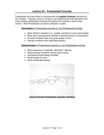
Lecture 24 – Prestressed Concrete Prestressed concrete refers to concrete that has applied stresses induced into the member. Typically, wires or “tendons” are stretched and then blocked at the ends creating compressive stresses throughout the member’s entire cross-section. Most Prestressed concrete is precast in a plant.
Introduction to Prestressed Concrete 1 / 7 In prestressed concrete, compressive stresses are applied to the concrete prior to loading. Under service loads, the entire cross section is essentially in compression, which takes advantage of concrete’s considerable compressive
prestressed concrete members, the bonding action between the prestressing element and the concrete is a result of friction as well as adhesion and mechanical resistance. In the fabrication of a pre-tensioned prestressed concrete member the prestressing strand is first tensioned to the desired stress level. Concrete is then cast about the strand and
Precast/Prestressed Concrete Institute, Design Handbook-Precast and Prestressed Concrete: Code of Standard Practice for Precast/Prestressed Concrete (PCI MNL-120) Structural Material Specifications Concrete Foundations (Pile Caps and Grade Beams): 6,000 p
As prestressed concrete became widely produced and adopted, a second concept was formulated, commonly known as the ultimate strength theory. Under that concept, prestressed concrete is treated as a combination of h\Ph strength con crete and high strength steel, with concrete to carry the compression
stressed concrete columns with the exception that our knowledge of re-inforced concrete columns may be utilized when dealing with pre-stressed ones. Three approaches are possible for the design of prestressed concrete columns: 1. Rational and analytical ap-proach. 2. A new set of code design clauses to be set up specifically for prestressed .
– Linear dynamic analysis Inelastic analysis – Nonlinear static analysis (pushover) – Nonlinear dynamic analysis Conventional design Advanced design. Structural model Frames structures can be model using linear elements (beams, columns, braces) connected in nodes Modelling of inelastic behavior of structural components must be accounted to perform a inelastic structural analysis Software .
a. prestressed box beam: 5 to 7 ksi b. prestressed I-beam: 5 to 7 ksi c. prestressed bulb-tee beam: 6 to 8 ksi An exception to the range shown above will be allowed for a higher strength if the higher strength can be documented to be of significant benefit to the project, it can be effectively
DPNS ASTM C823-12:2021 New Circulation 91.100.30 BPS/TC 5 Concrete, Reinforced Concrete and Prestressed Concrete Standard Test Method for Measuring Length of Concrete Cores DPNS ASTM C1542 / C1542M:2021 New Circulation 91.100.30 BPS/TC 5 Concrete, Reinforced Concrete and Prestressed
ASTM C823-12 (2017) New Drafting/Deliberation 91.100.30 BPS/TC 5 Concrete, Reinforced Concrete and Prestressed Concrete Terminology for Nondestructive Examinations ASTM E1316-19b New Drafting/Deliberation 91.100.30 BPS/TC 5 Concrete, Reinforced Concrete and Prestressed Concrete Practice for P
PS14 - Prestressed Concrete I Beam Last Modified: 3/13/2018 1 PS14 - Prestressed Concrete I Beam Example This example details the data input of a prestressed concrete I beam bridge and performing an analysis. This example is a bridge from the Mississippi DOT inventory which includes two units of SR 429, a three-span (138 ft each)
STATE OF THE ART FOR LONG SPAN PRESTRESSED CONCRETE BRIDGES OF SEGMENTAL CONSTRUCTION Segmental prestressed concrete bridges are described in terms of cross-sectional shape, layout of tendons, casting procedures, jointing techniques, and design details. Techniques of analysis for structures of this type are reviewed. Prospects for use of this
This article will therefore recommend solutions for continuous prestressed concrete bridge design in turnout zones, and continuous length over 300 m. It will suggest the configuration essentials of continuous prestressed concrete bridge design in turnout zones through an analysis of temperature changes and various types of bridge load.
Inelastic static analysis, or pushover analysis, has been the preferred method for seismic performance evaluation due to its simplicity. It is a static analysis that directly incorporates nonlinear material characteristics. Inelastic static analysis procedures include Capacity Spectrum Method, Displacement Coefficient Method and the Secant Method. (sermin, 2005). International Journal of .
Inelastic static analysis, or pushover analysis, has been the preferred method for seismic performance evaluation due to its simplicity. It is a static analysis that directly incorporates nonlinear material characteristics. Inelastic static analysis procedures include Capacity Spectrum Method, Displacement Coefficient Method and the Secant Method(Sermin,2005).The performance based earthquake .
The idea of prestressed concrete has been around since the latter decades of the 19th century, but its use was limited by the quality of the materials at the time. It took until the 1920s and ‘30s for its materials development to progress to a level where prestressed concrete could be used with confidence. Freyssinet in France, Magnel in
PRESTRESSED CONCRETE CONTAINMENT MODEL By Sami H. Rizkallal 1 A. M. ASeE, Sidney H. Simmonds,2 and James G. MacGregor/ Members, ASeE AeSTRACT: The construction and testing of a model of a prestressed concrete containment structure is described. The test structure consisted of a reinforced
Reinforced concrete and prestressed concrete are now mixed together in the code. Common material is now in “toolbox” chapters. There is no separate chapter on prestressed any more. PCI Design Handbook 7th Ed (covers pretensioned) based on ACI 318-08/11 8th Edition came out in 2018; based on ACI 318-14 NCEES no longer names a PCI Handbook
performance of prestressed concrete buildings, Then, for five typical prestressed concrete buildings, results of analyses of the dynamic response, with due consideration of the soil structure interaction, are presented. In general, the computed response of the buildings under the effect of . a . ground motion
established a committee in 1958 to prepare a standard for the design and construction of circular prestressed-concrete water storage tanks. The committee submitted a suggested specification covering wire-wound prestressed-concrete tanks to NEWWA in October 1962 as a guide to those water utilities that wished to consider the use of these tanks.
HiCAMS Review Prestressed Concrete 8-6 - 13 Results Tab Step 27: Continue entering your Field Inspection Report by clicking on the Results tab. The following tabpage is displayed. Figure 27 - Prestressed Concrete Results Tab Step 28: Select the strength of the material being inspected by clicking one of the Material Strength radio buttons. The
AASHTO CFRP- Prestressed Concrete Design Training Course Design of Pretensioned Concrete Bridge Beams with Carbon Fiber- Reinforced Polymer (CFRP) Systems 3 1. Introduction & References 2. Prestressing CFRP 3. Flexural Design 4. Shear Design 5. Prestressed Piles 6. Design Examples COURSE OUTLINE 3. FLEXURAL DESIGN 5 FLEXURAL DESIGN
The use of precast concrete segments, erected, and prestressed, offers a practicable, expeditious, and economical way of building long span bridges. . stressed concrete arch-cantilever of 492 feet. i. Bridge across Danube River at New Garden, Yugoslavia, with prestressed arch spans of 690 feet and 543 feet. The efficient construction of long .
complex application for designing prestressed concrete beams are pre-sented. The spreadsheet application presented is ideally suited to making preliminary design decisions quickly and efficiently, leading to better and more cost effective prestressed con-crete designs. posed to spreadsheets, the followin
Structural design of the prestressed concrete poles shall be the responsibility of the manufacture according to the data submitted by the user. 5.2 Design Criteria 5.2.1 General Length of prestressed concrete poles: The length of the pole is measured in meters between the two extremities.
Problem: A highway overpass consists of 3 parallel continuous prestressed concrete beams. The length of the overpass structure is 292.8 ft, with a width of 47 ft (Fig. 1 and 2). Each prestressed beam had 5 strands of prestressing steel. There were 22 wires in each strand and each wire had a diameter of 0.6 in. The end of each prestressed beam was
Prestressed Concrete – Shear Keys, Post-tension & Epoxy Overlays 2018 Bridge Construction Inspection School Chuck Snyder VDOT Staunton District Bridge Maintenance Specialist Handling, Storing & Erecting Prestressed Members 2016 Road and Bridge Specifications Section 405.05 (h): Shear keys and recesses shown on plans shall be filled with .
of statically indeterminate beams. Assumptions which are usually made in both simple prestressed concrete beams and continuous prestressed concrete beams are giv-en in Moorman's paper'. These as-sumptions are 1. Hooke's Law is valid 2. The principle of superposition holds 3. The
Structural Systems (A TLSS) on gravity load floor systems for precast/prestressed concrete buildings. The main objective of the research is to develop precast/prestressed concrete floor systems for gravity loads for application in occupied office buildings with a regular spacing of columns. Five proposed concepts for precast/ prestressed
Founded in 1954, The Precast/Prestressed Concrete Institute (PCI) is a technical institute for the precast concrete structures and systems industry. PCI develops maintains, and disseminates the Body of Knowledge for the design, fabrication, and construction of precast concrete structures and systems. PCI develops consensus
Mary Beth D. Hueste (2003) [7] has recommended that design parameters in the AASHTO specifications need to be modified for use with high strength concrete because the current design equations in the AASHTO specifications for prestressed concrete members are based on mechanical properties of normal concrete strengths of 6000 psi or less. .
A comparison has been made between the 96-in pre stressed concrete pipe furnished at Cross Canyon, based on 0-load equivalency, and a 10000 reinforced concrete pipe. By using Paris coefficients and the working stress method, for a prestressed concrete pipe designed for a field load of 230 000 lb/lineal
Typical w/cm ratio* 0.35-0.40 for precast concrete. 0.35-0.40 for precast concrete. 0.40-0.45. Confinement of strand Bonded prestressed strands are more protect-ed from corrosion, especially in concrete with lower w/cm ratios. Structural damage due to corrosion or severing of a prestressed strand is localized to an individual precast concrete
majority of traditional design challenges (Precast/Prestressed Concrete Institute, 2010). Various uses of precast concrete exist in the form of double and single tees, slabs, panels, beam and girders, stairs, and columns (Canadian Precast/ Prestressed Concrete Institute, 2007) (Figure :1). In South Africa, precast floor systems are the most com
to shrinkage of the concrete and other fac tors. Normally under these conditions a decrease in camber would be expected, but in a prestressed concrete beam the opposite occurs. The camber of the beam will con tinue to increase as a function of time. This phenomenon is believed to be principally thE effect of creep in the concrete.
prestressed concrete, three-wythe sandwich wall panels Byoung-Jun Lee and Stephen Pessiki Typical precast concrete sandwich wall panels comprise two con-crete wythes separated by an insulation layer. In this paper, such panels are referred to as two-wythe panels. Often, both concrete wythes are of the same thickness, and the surface of the exterior
considered to be price inelastic if a 1-percent increase in price brings about a less than 1-percent decrease in volume. If a product is price inelastic, a price increase will increase gross revenue. If we can confidently conclude that the demand for a product is inelastic with respect to price, then price increases can be a powerful financial .
stantially to interfacial transport. In this case, the predictions from the DMM become highly inaccurate. In this paper, the effects of inelastic scattering on thermal boundary conductance at metal/dielectric interfaces are studied. Experimental transient thermore-flectance data showing inelastic trends are reviewed and compared to traditional .
to prediction of fission, capture, elastic and inelastic scattering cross sections at 1 keV – 5 MeV energy range for fissile minor actinide nuclides. Major source of discrepancies in case of inelastic scattering on 232Th or 238U targets are the coupling strengths of the deformed optical potential [6, 7]. Experimental data on inelastic neutron
Momentum is conserved in all collisions Elastic collisions: no deformation occurs Kinetic energy is also conserved Inelastic collisions: deformation occurs Kinetic energy is "lost" Perfectly inelastic collisions Objects stick together; kinetic energy is "lost" Explosions Reverse of perfectly inelastic collisions;


