Inverter - Banggood
InverterAT1--Single-phase to three-phaseAT2--Single-phase to single-phaseAT3--Three-phase to three-phaseAT4--Single-phase to three-phaseAT Simple general seriesHigh performance and low noise/Mini AC motor driver
Charter 1 Installation and wiring1. Main circuit terminal and function description(1) Single-phase to three-phase (for AT1,AT4)TerminallabelFunction descriptionL, NSingle phase AC 220V input terminalOutput terminal connect to Three phase(220V-AT1) (380V-AT4)AC motorGrounding terminalU, V, WGND(2) Single-phase input and output (for AT2)Terminal labelFunction descriptionL, NSingle phase AC 220V input terminalOutput terminal connect to Singlephase 220V AC motorGrounding terminalU, V, WGND2页
(3). Three-phase input and output (for AT3)TerminallabelFunction descriptionR,S,TThree phase AC 380V input terminalOutput terminal connect to Three phase380V AC motorGrounding terminalU, V, WGND2. Terminal V/24V15V/24V power output200mA15V/24V outputX6Input port6(Reversing switch)Short Port X6 and COM, input signaleffectiveX5Input port 5 (Reverserotation Control switch)Short Port X5 and COM, input signaleffectiveX4Input port 4(Forwardrotation Control switch)Short Port X4 and COM, input signaleffectiveInput port 3(sectionspeed 3)Input port 2(sectionspeed 2)Input port 1(sectionspeed 1)Short Port X3 and COM, input signaleffectiveShort Port X2 and COM, input signaleffectiveShort Port X1 and COM, input signaleffectiveX3X2X1485 /485-485 communication port3页
FunctionaldescriptionInstructionsCommon GNDExternal analog voltageinput0-5V/10V Analog voltage inputCIExternal current signalinput4-20mA Current inputSP1Open-collector output 1SP2Open-collector output 25V/10V5V/10V power outputTCRelay output CTBRelay output BTARelay output APortCOMVL1supply 5V/10V 20mA power output250VAC 5A/30VDC 3ATA and TB Normal Close ,TA and TCNormal Open3. Multi-speed input Frequency control table :SectionSectionSectionOriginalspeed input 1 speed input 2 speed input 3 FrequencyMain Speed11150Section speed 111045Section speed 210140Section speed 310035Section speed 401130Section speed 501025Section speed 600120Section speed 711115Note:0 means input Port connect with COM, 1 meansdisconnect.4页
4. Basic operation wiring diagram(1) Single-phase input three-phase output (for AT1 )(Three phase 220V, if 380V Star-connection methodneeds to change to the 220V Delta-connection method)5页
(2). Single-phase input and output (for AT2)(220V single phase motor, Non-removed capacitor/ Removed capacitor)6页
(3). Three-phase input and output (for AT3)(380V three phase input, connect with 380V threephase motor)7页
5. Operation panel8页
6. Keys instructions:Icon12(Programming)Function descriptionFor selecting mode or Programming mode (it isavailable not mater the Inverter start or stop),press this key for modifying parameters.Function data setting key. Normal mode: pressthis key to display the information of the Inverter,(Function / Save)such as target frequency, output frequency andcurrent, temperature;Parameter3Key( )Key4( )number orShort press this key, thenthe numerical value willincreasechange gradually. LongParameterpress this key, then thenumber ornumerical value will changerapidlyparameter valueparameter valuedecreaseShift in programming mode, jog in normal modeShiftForward / Reverse switching key6 Forward / Reverse578NoteStartStop / ResetStart Inverter outputBreak down, fault resettingPlease modify the parameters under the stop state, otherwise, thechanged parameters cannot be saved.9页
Chapter 2 Parameter specification1. Parameter ter rangeDefaultUnitP00Maximum voltage0---220.0/380.0220/380VP01Reference frequency0---400.050HzP02Intermediate ency0---400.025HzP04Minimum voltage0---220.0/380.00VP05Minimum frequency0---400.00HzP06Maximum operating0---400.065.0HzP07Minimum operating0---400.00HzP08Hide password0---6553500000P09Input password0---655350P10Working frequencysourceP11Start/stopcontrol source0:1:2:3:Panel keyboard;Panel potentiometer;External analog signalRS485.10: Panel keyboard;1: RS485;02: External port.10页
0: Inertial stop;P12Stopping Modes1: Deceleration stop;12: Brake stop;3: Emergency brake.P13Braking time0---2.50.5SP14Braked Voltage0---140.020VP17Machine number1-2551P18Operating arrival0---100.050P20Over temperatureprotection selection1---8080P21Revolution for 50Hz0-800028001---10 (1-20 for High Ver)101---10050.1Hz0.1---60.03SP22Carrier settingFrequency adjusting stepP23sizeOverload protection bufferP24timeHzP26Working frequency0---400.050HzP27Section speed 1 setting0---400.045HzP28Section speed 2 setting0---400.040HzP29Section speed 3 setting0---400.035HzP30Section speed 4 setting0---400.030HzP31Section speed 5 setting0---400.025HzP32Section speed 6 setting0---400.020Hz11页
P33Section speed 7 setting0---400.015HzP34Main rising velocity1---100025Hz/SP351st rising velocity1---100025Hz/SP362nd rising velocity1---100025Hz/SP373rd rising velocity1---100025Hz/SP384th rising velocity1---100025Hz/SP395th rising velocity1---100025Hz/SP406th rising velocity1---100025Hz/SP417th rising velocity1---100025Hz/SP42Main descent velocity1---100025Hz/SP431st descent velocity1---100025Hz/SP442nd descent velocity1---100025Hz/SP453rd descent velocity1---100025Hz/SP464th descent velocity1---100025Hz/SP475th descent velocity1---100025Hz/SP486th descent velocity1---100025Hz/SP497th descent velocity1---100025Hz/S0: invalid, terminal isnon-functioningP50Multi function input 1 1: wire control stop(X1 binding post)2: keying stop;3: keying operation;4: stop keying;12页
P50 Multi function input 1(X1 binding post)P51Multi function input 2P52Multi function input 3P53Multi function input 4P54Multi function input 5P55Multi function input 65: wire forward operation6: wire reverse operation;7: reservation8: error reset signal;9: wire reversing switch;10: keying forward switching;11: keying forward switching;12: reverse switch keying;13: section speed input 1;14: section speed input 2;15: section speed input 3;16: external error signal.17: Jog Forward;18: Jog Reverse;19: Emergency stop;20: Relay Control.P62Multi function input 2Display options14155690: invalid, no output;1: operating instructions;Multi function input 1 2: set arrival instructionsP583: fault indication;(SP1)5: Emergency stop;6: For P50---P55 20;P60130Idem (Relay output)00: setting frequency;1: operating frequency;2: revolution 3: current;4: temperature; 5: time;013页
0: normal power on;1: report error with start signalwhen power on;2: Power on forward;3: Power on reverse.0P65Power on optionsP66Input stabilization time0---6553560P67Voltage coefficient0---6553528500P68Under voltage setting0---220/38060/180VP69Overvoltage setting220.0---400/680400/600VP700: P72 is compensation amount;1: Multiply P72 by P71 after P71minus input voltage0P76Torque compensationoptionsTorque compensationvoltageTorque compensationsettingMaximum externalanalogMinimum externalanalogZero currentcompensation valueCurrent coefficientP77Parameter 55350(It is the reset when 54321)0-655353000P78Main current overloadmAP79First current overload0-655353000mAP80Second current overload0-655353000mAP81Third current overload0-655353000mAP82Fourth current overload0-655353000mAP83Fifth current overload0-655353000mA14页
P84P85P86P87P88P89Sixth current overloadSeventh current overloadJog forward frequencyJog reverse frequencyJog rising velocityJog descent velocityP90 Jog stopping modesP91 Jog braking timePhase options (AT2P92only)The frequency ofP98closing the U-phase (AT2)P127Remaining 0000: Inertia stop;1: Decelerate stop;2: Braking stop;3: Emergency brake.0---2.50:Three-phase2:Three-line single phase3000 mA3000 mA20Hz20Hz50 Hz/S50 Hz/S10.1S00-50Hz00---6553565535HzH2. Parameter setting password and Down time stop:P08 is the hidden password, it always shows only 00000, not the actualvalue.When input the value of P09 the hidden value of P08, the P08 showshidden value, and the P08 and other parameters can be changed. TheP09 will be nullified when unplug the power cable to restart.When P127 65535, the function of countdown do not start.When P127 65535, the function of countdown will start, the P127will minus 1 when the Inverter runs for one hour. The frequencyconverter will be stopped when the countdown of P127 to 0 hour.15页
4. Parameter setting procedure:1. Press the programming key to enter into the programming state;2. Use the arrow keys and shift key to find the parameters thatneed to be modified;3. Press function / save key to enter into the parameter;4. Use the arrow keys and shift key to amend the parameter value;5. Press the function / save key to store the parameter;6. Press the programming key to exit the programming state.Chapter 4 Fault CodeFault Code DisplayFault Code DescriptionShort Circuit/Current overload/PowerErr 1Module protectionErr 2Undervoltage protectionErr 3Overvoltage protectionErr 4Driving Circuit FailuresErr 5Input at startup when electrifiedErr 6Over current protectionErr 7OvertimeErr 8Excessive temperatures for radiatorErr 9External fault16页
Charter 1 Installation and wiring (2) Single-phase input and output (for AT2) Terminal label Function description L, N Single phase AC 220V input terminal U, V, W Output terminal connect to Three phase (220V-AT1) (380V-AT4)AC motor GND Grounding terminal Terminal label Function description L, N Single phase AC 220V input terminal
Switches the inverter ON or OFF, resets the inverter 5.2 Inverter Status LED's 5.2.1 Inverter Switched Off 5.2.2 Inverter Switched ON 5.2.3 Overload "STATUS LED" Blinking indicates that the inverter is switched off. "STATUS LED" steady ON and the other LEDS rotating in a clockwise direction indicates that the inverter is switched on a
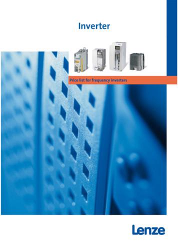
Then Lenze is the partner you are looking for. For more than 60 years, drive and automation systems have been our core competence. 3 Contents Inverter Drives 8400 4 Inverter Drives 8400 motec 18 Inverter Drives 8400 protec 20 8200 vector frequency inverter 24 8200 motec frequency inverter 54 9300 vector frequency inverter 60. Price list .
LK/LW Series Power Star inverters Ensure that the inverter is switched off during the installation. It is recommended that you always connect the inverter to the battery bank first, as the battery power ultimately starts the inverter. If the inverter is connected to the AC input only, with the batteries disconnected or too low, the inverter .
PV Grid Tie Inverter Installation and Operation Manual Solis 4G Single Phase Inverter Ver 1.0-US version Solis-1P6K-4G-US, Solis-1P7K-4G-US, Solis-1P7.6K-4G-US, . To startup the inverter, the Grid Supply Main Switch (AC) must be switched on, before the solar panel's DC isolator shall be switched on. To stop the inverter, the Grid Supply
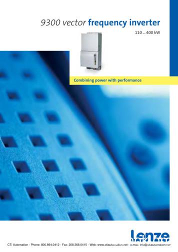
9300 servo inverter 8200 vector frequency inverter 8200 motec motor inverter starttec motor starter ECS servo system for multi-axis application Communication modules . Lenze has designed the 9300 vector frequency inverter for this type of applica-tion. The range supports powers from 110 . 400 kW and features optimised
This manual is valid for following HF inverters: HF Inverter e@syDrive 4624 Material no. 2.002.1053 HF Inverter e@syDrive 4624 IP00 Material no. 2.002.6308 HF Inverter e@syDrive 4624 IP00-S Material-Nr. 2.003.0591 HF Inverter e@syDrive 4625 Material no. 2.002.1054 HF Inverter e@syDrive 4626 Material no. 2.002.1055 3.0 Connections
Inverter practice course Explains the inverter principle, the precautions for using an inverter, etc. in an understandable way. You can understand the functions, performance, etc. of an
Figure 10 Bracket Installation Step 3: Mount inverter onto the narrow vertical panel , ensure upper corner of the inverter is hooked onto the bracket, use M5 screws to fix the lower part of the inverter to the bracket (See figure 10). Step 4: Use M5 flange nut to fix the bottom of the inverter. Step 5: Complete the installation process.


