Process Control And Instrumentation Technology Model:
Process Control and Instrumentation TechnologyModel: PCT-200IntroductionThe PCT-200 Process Control and Instrumentation rig provides a self-contained process control systemwhich is representative of many industrial process control systems that are used in the chemical, oil, food,water and other process industries. The rig is fitted with state-of-the-art intelligent process instruments andactuators which are networked via PROFIBUS PA and DP to communicate with a Programmable LogicController (PLC).The controlling PLC can be configured to implement a number of different control strategies for flow andlevel control using cascade, feed-forward and multi-variable strategies. The rig also provides separate levelalarms and process and device temperature monitoring. Further, the control system is linked via an EthernetLocal Area Network (LAN) to a modern PC platform and gateway which provides modern SupervisoryControl and Data Acquisition (SCADA) monitoring and control of the process. Asset management tools arealso available on the PC workstation for calibration, diagnostics, predictive maintenance and otherengineering instrumentation and actuation tasks. Bytronic LtdPCT-200-DS091
Basic Process and InstrumentationFigure 1 shows the basic rig Process and Instrumentation (PI) diagram. A reservoir holds water which ispumped by a speed-controlled centrifugal pump (SC) to the rest of the process. The three-phase motor thatdrives the pump is controlled using a networked variable frequency inverter.The pump outflow passes through a venturi-tube which provides flow measurement via a differentialpressure transmitter (DP). The venturi outlet normally passes to tank 1, however the manual ball valves canoptionally be set to bypass tank 1 and direct the flow to a modern electromagnetic flow transmitter (FT).This arrangement means that this highly accurate flow meter can be used for calibration and measurementof the orifice characteristics. Optionally, a pressure transmitter (PT) can be fitted to measure the pumpdischarge pressure and can be used to enable experiments on centrifugal pump characteristics.The pump speed control can be used in conjunction with the DP transmitter for flow control, or inconjunction with the level transmitter (LT) for level control in tank 1. A cascade control system can also beimplemented by feeding the level controller output as a set-point to the flow controller. A temperaturetransmitter (TT) is provided in tank 1 for monitoring of the water temperature. This cannot be used forcontrol, but is useful for demonstrating various aspects of instrumentation. The differential pressuretransmitter (DP) mounted beneath tank 1 which can be used to provide level measurement. The differentialpressure transmitter can also be used in conjunction with a venturi for flow measurement in the line fromthe pump to tank 1.The outlet of tank 1 passes to tank 2 via a state of the art electromagnetic flow meter (FT) and then to amodulating control valve fitted with a pneumatic positioner (XV). The control valve can be used inconjunction with the flow transmitter for flow control, or in conjunction with the ultrasonic leveltransmitter (LT) for level control in tank 2. The outflow from tank 2 back to the reservoir is controlled by acalibrated hand-operated ball valve.OverflowLTTank 1TTXVTank 2FTManual ballvalvesReservoirCentrifugalpump withspeed controlPTDP cell providing alternatelevel or flow measurementDPVenturitubeSCFigure 1 – Basic Process and Instrumentation diagram for the PCI rig Bytronic LtdPCT-200-DS091
NetworkingFigure 2 shows the rig network layout. All instrumentation and actuation is provided with PROFIBUS(PROcess-FIeld-BUS) connectivity. The centrifugal pump speed control is provided by a modern variablefrequency inverter with integrated PROFIBUS DP interface. All the process instruments are provided withintegrated PROFIBUS PA connectivity. A DP/PA coupler provides a transparent gateway from DP to PA.The PLC incorporates a PROFIBUS DP master which controls cyclic communication with all the fielddevices. Cyclic data is used for all process data.The PLC is also provided with an Ethernet interface which enables networking to the PC workstationwhich runs SCADA software. The gateway provides another route from Ethernet to PROFIBUS forengineering data. This is used with asset management software for reading and writing device parameterswithin the field devices. This software has facilities for device configuration, calibration, diagnostics,health checking and predictive maintenance.PC WorkstationEthernetPLC/IPCGatewayPROFIBUS DPInverterDP/PA CouplerLTTTFTDPXVPTFigure 2 – Rig networking Bytronic LtdPCT-200-DS091PROFIBUS PA
Laboratory WorkThe rig has many possibilities for practical work, exercises and project work. These are concerned with the areas ofinstrumentation and calibration, process control, instrumentation management and maintenance and networking. Thefollowing list outlines some of the many possibilities for laboratory worka.b.c.Temperature measurementi.Temperature measurement and status indicationii.Scale and alarm limit setting, simulation mode for intelligent sensors.iii.Sensor and transmitter diagnostics.Level measurementi.Hydrostatic level measurement and calibration, effects of density.ii.Ultrasonic level measurement and calibration.iii.Ultrasonic reflection envelope curve and problem diagnosis.Flow measurementi.Volume and mass flow measurement using electromagnetic flow meter.ii.Flow meter calibration.iii.Flow rate measurement using a differential pressure transmitter and orifice plate.iv.Square root extraction within an intelligent transmitter.v.Calibration and performance of a head meter.vi.Process noise in flow measurement.Actuation elements and characteristicsd.Control valvei.Valve positioner operation and calibration.ii.Valve sizing calculation and verification.iii.Measurement of valve installed characteristic.iv.Fail-safe action in the event of pneumatic or electronic failure.e. Inverter, Motor and Centrifugal pumpi.Induction motor speed control and characteristicsii.Setting up a drive over PROFIBUS.iii. Centrifugal pump speed/flow/head characteristic measurement.Feedback control systemsf.g.h.Level controli.Control of level using variable pump speed.ii.Control of level using control valve.iii.P, PI and PID level controller tuning and performance.Flow controli.Flow control using variable pump speed.ii.Flow control using a control valve.iii.P, PI and PID controller tuning and performance.Cascade and feed-forward controli.Cascade control of level and flowii.Feed-forward control using flow measurementiii.Multi-variable control of level and flow.Fieldbus systemsi.j.PROFIBUS system configuration for cyclic datai.Basic DP device configuration, GSD files, modules and parameters.ii.Bit-rate selection and cycle time effects.iii.PA system configuration, process value and status byte handling.iv.Diagnostics, watchdog timer setting and fail-safe action.Acyclic communicationsi.Use of engineering tools with acyclic communication capability.ii.Device profiles: physical, transducer and function blocksiii.Methods of device calibration using acyclic communicationsiv.Advanced device diagnostics and statusv.Auto, manual and simulation modes of operation for transmitters and actuators.vi.Predictive maintenance features in a modern control valve positionervii.Predictive maintenance features in a modern inverter.Ethernet and LAN technologyk.Network configuration and checkingi.MAC and IP addressing, setup and checkingii.PC networking diagnostic facilities.iii.Remote device configuration using http (web) technology. Bytronic LtdPCT-200-DS091
Pump and pipe sizingThe nominal maximum flow rate around the system is 20 litre/min 0.3 litre/s. The pump delivers a linearflow/head and flow/speed characteristics. At a speed of 2900 rpm (50 Hz), the pump delivers a maximumhead of 16m ( 1.6bar) at zero flow dropping to 2m at 16 litre/min. All pipe work and valves are 1” nominalbore schedule 40 clear UPVC piping. The rated working pressure of this piping is 15.2 bar, giving a safetyfactor of almost 10. The internal diameter of this pipe is Flow/(litre/min)141618Pump characteristics at various pump speedsVenturi and DP cell sizingA venturi tube (according to EN 5167-4) provides flow measurement for the pump delivery. The maximumdifferential at a flow rate of 16 litre/min is about 0.6m and the overall loss is about 0.1m. The DP cellincorporates a function block which can calculate the square root of the differential pressure and scale themeasurement to give the flow rate.0.80.70.6Delta P/m0.5Delta ri tube characteristic Bytronic LtdPCT-200-DS0911618
Ordering Information:Model Number:Consists of:Air Supply requiredMains supply requiredPCT-2001 x PCT-200 Process Control and Instrumentation RigControl CabinetDP/PA couplerUltrasonic level transmitter (LT)Temperature transmitter and thermowell (TT)Differential pressure transmitter (DP)Electromagnetic flowmeter (FT)Pressure Transmitter (PT)Global control valve (XV)Venturi tube and parts3 phase InverterPROFIBUS Master PLC IPCEthernet/PROFIBUS DP gateway (Fieldgate)Inverter PROFIBUS DP interfaceSix-way PROFIBUS PA segment protectorAsset Management Software (Fieldcare)SCADA softwareEthernet switchPLC configuration and programming softwarePipes are 1 inch clear6 Bar continuous supply240v AC Single PhaseShipping InformationWeight (unpacked) netDimensions (unpacked) cmWeight (packed) grossDimensions (packed) cm150kg176 L x 70 W x 195 H320kgs (Tarre weight 170 kgs)192 L x 88 W x 218 HNotes.1.2.Specification is subject to change without notice.All dimensions are in mm unless specified otherwise.Bytronic Ltd., reserves the right to make product improvements at any time and without notice and is not responsible fortypographical errors. Bytronic Ltd., recognise all product names used herein as trademarks or registered trademarks of theirrespective holders. Bytronic LtdPCT-200-DS091
Bytronic LtdPCT-200-DS091
124 Anglesey Court, Towers Business Park, Rugeley, Staffordshire, WS15 1UL, UKTel; 44(0)8456 123 155Fax; 44(0)8456 123 156www.bytronic.net Email; sales@bytronic.net Bytronic LtdPCT-200-DS091
Process Control and Instrumentation Technology Model: PCT-200 Introduction The PCT-200 Process Control and Instrumentation rig provides a self-contained process control system which is representative of many industrial process control systems that are used in the chemical, oil, f
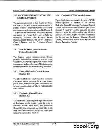
3.0 PROCESS INSTRUMENTATION AND CONTROL SYSTEMS The systems discussed in this chapter are those that have to do with process instrumentation or process control. The control systems used to alter reactor core reactivity are discussed in Chapter 7. The process instrumentation and control
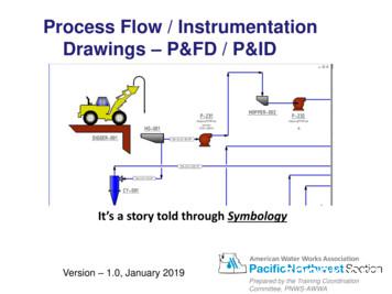
The Process & Instrumentation Diagram Process & Instrumentation Diagram (P&ID) show what is in the PFD –plus the instrumentation to monitor the process –plus how it is controlled. A P&ID shows the relationships between the all components in the system and shows details. Version - 1.0, January 2019 Process Flow / Instrumentation .
The Process & Instrumentation Diagram Process & Instrumentation Diagram (P&ID) show what is in the PFD -plus the instrumentation to monitor the process -plus how it is controlled. A P&ID shows the relationships between the all components in the system and shows details. Version - 1.0, January 2019 Process Flow / Instrumentation .
Change Control in SmartPlant Instrumentation - Because of the Critical and Dynamic nature of process data it is important that Change Management Procedures be in place on every project. - The Process Engineer is the Owner of the Process Data in SmartPlant Instrumentation Process Training for SmartPlant Instrumentation
Process Control (2001)in which the basics of instrumentation were given along with some applications of instruments and control systems to real processes. Because the present work is an extension of this latter aspect, it is therefore confined mainly to the techniques of applying instrumentation and control systems to manipulate the process to
Lab 6: Instrumentation Amplifier . INTRODUCTION: A fundamental building block for electrical measurements of biological signals is an instrumentation amplifier. In this lab, you will explore the operation of instrumentation amplifiers by designing, building, and characterizing the most basic instrumentation amplifier structure.
Process Control Networks SCADA, DCS, Fieldbus, Foundation Fieldbus, wireless sensors Text Books: i. Process Control Instrumentation Technology by Curtis Johnson, 4th Edition, PHI. ii. The Condensed Handbook of Measurement and Control by N. E. Battikha, 3rd Edition, ISA iii. Fieldbuses for Process Control: Engineering, Operation and Maintenance,
Grade 2 Indiana Academic Standards 2014 3 . READING: Literature. There are three key areas found in the Reading: Literature section for grades 6-12: Key Ideas and Textual Support, Structural Elements and Organization, and Synthesis and Connection of Ideas. By demonstrating the skills listed in each section, students should be able to meet the Learning Outcome for Reading: Literature. Learning .


