VOLUNTARY SAFETY RECALL CAMPAIGN 2013 ALTIMA OCS
Reference:Dat e:NTB13-033April 2, 2013VOLUNTARY SAFETY RECALL CAMPAIGN2013 ALTIMA OCS SENSORSCAMPAIGN ID #:PC214NHTSA #:13V-069APPLIED VEHICLES: 2013 Altima (L33)Check Service COMM to confirm campaign eligibility.INTRODUCTIONNissan is conducting a Voluntary Safety Recall Campaign to replace the OccupantClassification System (OCS) sensors on certain specific 2013 Altima vehicles at no chargefor parts or labor.IDENTIFICATION NUMBERNissan has assigned identification number PC214 to this campaign. This number mustappear on all communications and documentation of any nature dealing with this campaign.DEALER RESPONSIBILITYIt is the dealer’s responsibility to check Service Comm for the campaign status on eachvehicle falling within the range of this voluntary safety recall campaign which for any reasonenters the service department. This includes vehicles purchased from private parties orpresented by transient (tourist) owners and vehicles in a dealer’s inventory. Federal lawrequires that new vehicles in dealer inventory which are the subject of a safety recallmust be corrected prior to sale. Failure to do so can result in civil penalties by theNational Highway Traffic Safety Administration. While federal law applies only to newvehicles, Nissan strongly encourages dealers to correct any used vehicles in their inventorybefore they are retailed.Nissan Bulletins are intended for use by qualified technicians, not 'do-it-yourselfers'. Qualified technicians areproperly trained individuals who have the equipment, tools, safety instruction, and know-how to do a jobproperly and safely. NOTE: If you believe that a described condition may apply to a particular vehicle, DONOT assume that it does. See your Nissan dealer to determine if this applies to your vehicle.1/16
SERVICE PROCEDURECAUTION: Handle interior trim carefully to avoid damage. Work with clean hands andclean tools to avoid dirt and stains. Use protective covers as needed.WARNING: This procedure involves working with the passenger seat frame. The metalseat frame has sharp edges.NOTE: Make sure to follow this procedure exactly as specified to ensure properoperation of the Occupant Classification System1. WARNING: Turn the Ignition OFF and prepare the vehicle for OCS sensor replacementas follows:The following are VERY IMPORTANT to prevent unexpected air bag deployment. Remove the ignition key / Intelligent Key from the cabin of the vehicle and setaside, away from the vehicle. This will prevent accidentally turning the ignitionON. Make sure the ignition remains OFF until after the procedure is complete. Wait for all control units to “power down” (at least 3 minute) after the ignitionis turned OFF.Rear hingecover2. Reach under the rear of the frontpassanger seat and disconect the rearhinge cover. The rear hinge cover is attactedunder the seat with an elasticstrap.Figure 12/16NTB13-033
3. Remove the seat cushion innerfinishers, left and right side, asfollows:NOTE: These finshers have twohalves. Only the inner half (seatcushion side) will be removed.Seat cushioninner finishersFigure 2a. Remove 3 screws from the finishers (see Figure 3). 2 from the left side 1 from the right side.Phillips headscrewsFigure 33/16NTB13-033
b. Use a plastic trim tool to separate the inboard half of each finisher.Figure 4c. Pull the inboard half of each finisher toward the rear of the vehicle to remove.Figure 54. Lock the seat tracks in a position about midway between forward and rearward.NOTE: In the next steps you will be removing the 14 mm nuts that hold the seat frame to theseat track. The seat track should not be moved while the 14 mm nuts are removed. The seat should be positioned so that work can be performed under the front of theseat and under the rear of the seat without moving the seat track.4/16NTB13-033
WARNING: This procedure involves working with the passenger seatframe. The metal seat frame has sharp edges.5. From under the rear of the passenger seat, remove the 14 mm nuts from the rear of theseat frame (see Figure 6).NOTE: These nuts will not be reused.Left side / inboard side of seatRight side / outboard side of seat14 mm nutsRear OCS sensorFigure 66. From under the front of the passenger seat, remove the 14 mm nuts from the front ofthe seat frame (see Figure 7).NOTE: These nuts will not be reused.Left side / inboard side of seat14 mm14 mmRight side / outboard side of seatFigure 75/16NTB13-033
7. Replace the front OCS sensor as follows:a. Lift the front of the seat to rock itback.Figure 8b. Remove the 12 mm nuts holdingthe sensor.OCS sensorNOTE: Do not reuse the 12 mmnuts.c. Remove the old sensor andInstall the new sensor.d. Use new 12 mm nuts. Torque nuts to:22 N m (3.04 kg-m, 16 ft-lb)Figure 9e. Render the old sensor unusableby breaking its electricalconnector.6/16NTB13-033
8. Replace the rear OCS sensor as follows.a. Lift the back of the seat to rock itforward.Figure 10b. Remove the 12 mm nuts holdingthe sensor.NOTE: Do not reuse the 12 mmnuts.OCS sensorc. Remove the old sensor andInstall the new sensor.d. Use new 12 mm nuts. Torque nuts to:22 N m (3.04 kg-m, 16 ft-lb)Figure 11e. Render the old sensor unusableby breaking its electricalconnector.7/16NTB13-033
9. From under the rear of the seat, install both rear 14 mm nuts finger tight only(see Figure 12). Use new nuts.Left side / inboard side of seatRight side / outboard side of seat14 mm nutsRear OCS sensorFigure 1210. From under the front of the seat:a. Install both front 14 mm nuts finger tight only (see Figure 13). Use new nuts.b. Torque 14 mm nuts as follows (see Figure 13):1st, torque the outboard 14 mm nut to 45 N m (4.56 kg-m, 33 ft-lb).2nd, torque the inboard 14 mm nut to 45 N m (4.56 kg-m, 33 ft-lb).Left side / inboard side of seat1st2ndRight side / outboard side of seatFigure 138/16NTB13-033
11. From under the rear of the seat, torque 14 mm nuts as follows (see Figure 14):1st, torque the inboard 14 mm nut to 45 N m (4.56 kg-m, 33 ft-lb).1st2nd2nd, torque the outboard 14 mm nut to 45 N m (4.56 kg-m, 33 ft-lb).Left side / inboard side of seatRight side / outboard side of seatFigure 1412. Connect the electrical connectors for both OCS sensors.Connect rearOCS sensorConnect frontOCS sensorFigure 159/16NTB13-033
13. Reinstall the seat cushion inner finishers. Make sure they are snapped in place securely and correctly. Reinstall 2 screws on the left side Reinstall 1 screw on the right side.Phillips headscrewsFigure 16Rear hingecover14. Reattach the rear hinge cover.Figure 1715. Operate the seat slide and make sure both tracks (left and right side) lock in place ateach adjustment point.16. Perform Zero Point Reset and check for DTCs; next page.10/16NTB13-033
Zero Point Reset / Check for DTCs1. Attach the CONSULT-III plus (C-III plus) VI to the vehicle.2. Prepare the vehicle for Zero Point Reset. Place the vehicle in a level area. Minimize vibrations near the vehicle. Remove any objects on the passenger seat. No occupants in the vehicle – including the servicing technician. Close all of the vehicle doors. Do not touch the vehicle during zero point reset.3. Place the CONSULT PC outside the vehicle and away from the vehicle.4. Open/start C-III plus.5. Wait for the plus VI to be recognized. The serial number will display when the VI is recognized.6. Select Diagnosis (One System).Step 5: VI isrecognizedStep 6Figure Z111/16NTB13-033
7. Select OCCUPANT DETECTION.Step 7Figure Z28. Wait for System Call to complete.9. Select Zero point reset function.10. Select Start.Step 9Step 10Figure Z312/16NTB13-033
11. Select Next.Step 11Figure Z412. Select Start.Step 12Figure Z5NOTE: Zero Point Reset must be performed even if: “Current status” indicates “Completed”, or “Zero point reset current status” indicates “Already performed”13/16NTB13-033
13. Wait for Zero Point Function to complete.Figure Z614. Make sure that “Current status” is Completed.Step 14Figure Z714/16NTB13-033
15. Select Home on C-III plus.16. Check for Air Bag DTCs.Navigate C-III plus to:Diagnosis (One System) Ö AIR BAG Ö Self Diagnostic Results No Air Bag DTCs stored – go to the next step. DTC B00A0 stored (current or past) – erase stored code, then go to the next step. Other DTCs stored: Refer to ASIST and the Service Manual for additional diagnosticand repair information. Issues other then replacement of the OCS sensors arenot coved by this campaign.17. Close C-III plus, turn the ignition OFF, and disconnect from the vehicle.18. Turn the ignition ON and observe the air bag warning light: Light should illuminate for 7 seconds and then go out.NOTE: If the Air Bag Warning light does not operate as described above there maybe an issue not covered by this campaign. Refer to ASIST and the Service Manualfor additional diagnostic and repair information.15/16NTB13-033
PARTS INFORMATIONDESCRIPTIONSen-Occupant(OCS Sensor)M10 Nut(14 mm wrench size)M8 Nut(12 mm wrench size)PART S INFORMATIONSubmit a “CM” line claim using the following claims coding:CAMPAIGN (“CM”) I.D.PC214DESCRIPTIONReplace Two (2) OCS Sensors16/16OP CODEPC2140FRT0.7 hrs.NTB13-033
NTB13-033 April 2, 2013 VOLUNTARY SAFETY RECALL CAMPAIGN 2013 ALTIMA OCS SENSORS CAMPAIGN ID #: PC214 NHTSA #: 13V-069 APPLIED VEHICLES: 2013 Altima (L33) Check Service COMM to confirm campaign eligibility. INTRODUCTION Nissan is conducting a Voluntary Safety Recall Campaign to replace the Occupant
Voluntary Life - minimum group size: 3 (depends on state) Voluntary Critical Illness - minimum group size: 10 Voluntary Dental - minimum group size: 5 Voluntary Vision -- minimum group size: 50 Health Net: Health Net offers voluntary dental, voluntary vision, and voluntary term supplemental coverage to groups of two or more. Voluntary .
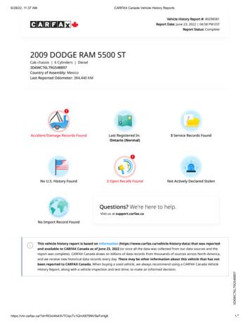
2015 May 8 DODGE Recall Manufacturer Recall Issued Recall # R16 2015 May 29 DODGE Recall Manufacturer Recall Issued Recall # R25 2016 Mar 7 Motor Vehicle Dept. Ontario, Canada Canadian Renewal Registration Issued or Renewed New Owner reported Previous Use: Commercial 2016 Jul 1 DODGE Recall Manufacturer Recall Issued Recall # S43
2013-2014 PATHFINDER ABS SOFTWARE UPDATE CAMPAIGN I.D. #: R1308 APPLIED VEHICLE: All 2013 - 2014 Pathfinder (R52) Check Service Comm to confirm campaign eligibility. INTRODUCTION Nissan is conducting a Voluntary Safety Recall Campaign on certain MY2013 -14 Pathfinder vehicles to reprogram the ABS control unit at no cost to the customer for parts or
IMPORTANT SAFETY RECALL NOTICE NHTSA Recall Number: 16V-542 School Bus NHTSTA Recall Number: 16V-543 Non-School Bus August 15, 2016 Dear Blue Bird Owner: Subject: RECALL R16YT, Propane Fuel Line Routing This important safety recall notice applies to your bus(es) identified by both Blue Bird Body Number and
2011 - 2012 QX56 AND M56 FUEL RAIL PRESSURE SENSOR CAMPAIGN ID #: R1202 NHTSA #: 12V-069 APPLIED VEHICLES: 2011 – 2012 QX56 (Z62) 2011 – 2012 M56 (Y51) Check Service COMM to confirm campaign eligibility. INTRODUCTION Infiniti is conducting this voluntary safety recall campaign on 2011 and 2012 model year QX56 and M56
2006 and 2008 Pathfinder (R51) Check Service COMM to confirm campaign eligibility. INTRODUCTION Nissan is conducting a voluntary safety recall campaign on certain MY2006 and 2008 Frontier, Xterra, and Pathfinder vehicles to address a potential fuel gauge inaccuracy.
Nissan is conducting a Voluntary Safety Recall Campaign on certain Model Year 2011 Rogue vehicles to inspect and, if necessary, replace the EPS (Electronic Power Steering) control unit. This service will be performed at no charge for parts or labor. IDENTIFICATION NUMBER Nissan has assigned identification number R1113 to this campaign. This .
Asset Management has now spread to many utility organizations and large and small companies are adopting similar programs. 3 The changing role of Maintenance Management in Asset Management: To illustrate how maintenance managers can contribute to an Asset Management improvement program, the table below lists some common issues facing management in the first column, and thoughts on how these .


