DUAL PISTON HYDRAULIC PUMPS
DUAL PISTONHYDRAULICPUMPSSERVICE MANUAL(Hi-Lo Two Speed, Hand or Foot Operated).STAR HYDRAULICS, INC.2727 CLINTON STREETRIVER GROVE, ILLINOIS m
In servicing hydraulic units, cleanliness is of the utmost importance.A clean work place and proper toolsare necessary to insure efficient andeffective repair. Special tools canbe furnished on request.AENOTE: Please specify pump modelnumber when ordering parts. If youare not sure of your pump modelnumber, call the factory and requesta pump model identification sheet befaxed or e-mailed to your. Pump partslists are also available for your model.CAONLY ONCP-15EDD DC-BDBDPRESSUREPORTDTypical assembly drawing of two speed pump showingsectional view location.TROUBLEPump will not hold pressurePump fails to supply pressurePump piston does not draw a full charge.(This is evident by a cushion effect at thetop of the pump stroke)POSSIBLE CAUSECORRECTIVE REPAIRINSTRUCTIONS1.Release valve ball not seating properlyRefer to “Release Valve” notes2.Ball valves not seating properlyRefer to “Pump Valve” notes3.Overload valve ball not seating properlyRefer to “Overload Valve” notes4.Large piston unloading valve seal faultyRefer to “Large piston unloading valve”1.Lack of oil2.Air bound pump3.Release valve ball not seating properly4.Small ball in valve circuit not seating properly5.Overload valve ball not seating properly6.Large piston unloading valve seal faulty1.Air bound systemRefer to “Air Bleeding” notes2.Lack of oilRefer to “Oil” notesRefer to “Oil” notesRefer to “Air Bleeding” notesRefer to “Release Valve” notesRefer to “Pump Valve” notesRefer to “Overload Valve” notesRefer to “Large piston unloading valve”Pump piston raises by itself under pressureLarge ball in ball valve circuit not seating properlyRefer to “Pump Valve” notesPump functions properly but will generateonly a given pressure below its normalpressure maximumOverload valve not properly setRefer to “Overload Valve” notesLarge piston unloading valve not set properlyRefer to “Large piston unloading valve”Pump fails to supply greater output at noload than under load.Air BleedingAir accumulation in a hydraulic system will cause erratic action. This may appear as pump failure to theinexperienced user. For this reason, it is advisable to air bleed each pump before attempting to operate. Toemove air from the pump, open release valve with the pump in an upright position. Operate the pump slowlythrough the full piston stroke about a dozen times. Close the release valve. Pump should be ready for use.
OilIf the pump fails to operate, check the oil level before attempting any repairs.The maximum fill level is 1 ½” below the inside of the reservoir cover.CAUTION: Use only hydraulic oil when refilling. NEVER USE BRAKE FLUID.Pump PistonLeakage of oil around the pump piston may indicate worn or damaged piston packings.To replace packings:a)b)c)d)e)Remove the piston actuating linkageRemove the piston. (See piston section drawing A-A)Remove all packings. (see piston section drawing A-A)Clean all parts and dry with compressed air.Install new packings, wipers, and static seals making sure that packing seal lips are face down toward thepressure. (Lubricate each part into clean hydraulic oil before assembly)f) Open the release valve (to allow air to bleed from the piston barrel back to the reservoir) and insert the piston.g) Replace piston linkage.h) NOTE: With release valve open, stroke pump about a dozen times to bleed air completely from the pump.Pump ValvesIf the pump fails to supply pressure or if the pump piston is under pressure at all times, the pump valves may needcleaning. Stand pump in an upright position. Remove the valve plug and seal. Tilt the pump to remove valvesprings and balls. Allow oil to drain from the reservoir through these valve holes to wash foreign matter from thevalve cavity. Lay pump on its side to clean and inspect valve chamber. Be careful not to mar or nick the ball valveseats. Clean the valve balls and springs in solvent. Replace rusted or corroded balls. Do not stretch the ballsprings. To reassemble, insert in sequence, the small ball, small spring, large ball, and large spring into thecleaned chamber. Finally, screw in valve seal plug. Note that the seal kit contains the new style valve plug andseal. This procedure should be carried out in all ball valve circuits. If the valves fail to operate properly after theyhave been cleaned, it may be necessary to reseat the valve balls. Remove the springs and tap each ball lightly inits respective seat using the ¼” ball seating tool (CP13-42) for the small ball and the 3/8” ball seating tool (CP13-43)for the large ball. Remove balls to make sure they are not stuck to the seats. Reassemble pump valves as before.See “Air Bleeding” instructions before attempting to operate the pump.Release Valve – Cam TypeIf the pump fails to lift or hold a load, the release valve may bedirty. From back of pump remove the release valve plug, releaseball spring and 3/8” release ball. From the front, remove therelease lever pin, release lever and release plunger and seal.Clean release valve chamber and inspect the ball seat. Ifnecessary, re-seat the release ball by tapping it lightly on the ballseat, using the 3/8” ball seating tool (CP13-43). Clean plungerand inspect the plunger packing and replace if necessary. Toreassemble, insert the ball, ball spring, and release valve plug.Lubricate the release plunger packing with hydraulic oil andcarefully insert into the plunger chamber. Re-install the releaselever and lever pin. See “Air Bleeding” instructions beforeattempting to operate the pump.
Release Valve – Screw TypeIf the pump fails to lift or hold a load, the release valve may be dirty.Remove the release screw, release valve seal and 9/32” release valveball. Clean and inspect valve seat and screw. A slight depression in theend of the screw is not harmful. Screws with excessive deformationshould be replaced. Re-seat the release ball using the ¼” ball seatingtool (CP13-42). To reassemble, insert the release valve packing usinginserting tool P1A-40. Reinstall the release screw. See “Air Bleeding”instructions before attempting to operate the pump.Overload ValveIf the pump fails to lift or hold a load after the release valve and pumpvalves have been checked, the overload valve may be dirty. To clean thevalve, remove valve plug and valve plug seal. Using a screwdriver,remove the overload valve screw, valve spring, valve plunger and steelball. Clean and inspect valve cavity. If the ball seat is marred, re-seatthe overload ball by lightly tapping the ball on seat using tool (CP13-45).Remove the ball to prevent sticking. Reassemble the ball, plunger, springand valve screw. Connect a pressure gage to the pressure outlet. Strokethe pump to obtain maximum desired pressure. Turn the valve screwclockwise to increase the pressure reading and counter-clockwise toreduce the maximum reading. After valve is set properly, replace valveplug. Note that the seal kit contains the new style valve plug and seal.See “Air Bleeding” instructions before attempting to operate the pump.Large Piston Pump Relief ValveIf the pump fails to lift faster under no load than it does under heavy load,the large piston unloading valve may be dirty. This valve is covered witha sealing compound to prevent tampering. Remove the sealingcompound, valve screw, spring and plunger with seals. Use threadedsocket tool (CP13-41) to remove plunger. Clean and inspect the valvecavity. Inspect the plunger packings and replace if necessary. Toreassemble, lubricate the plunger seals with hydraulic fluid and carefullyinsert it back into the valve cavity taking care not to damage the seals.Reassemble the spring and valve screw. Tighten the screw to obtain thedesired effort on lever bar at large piston change-over point. If the screwis tightened too far it will restrict the unloading valve movement and causeexcessive handle effort throughout the high pressure cycle.
STAR HYDRAULICS, INC.Hydraulic oil recommendations for Star Hydraulic hand and foot pumps.Typical test dataGravity29Flash234 FFire380 FViscosity at 100 F80 S.U.S.Viscosity at 210 F37.4 S.U.S.Average Viscosity Index75PourMinus 55 / 60 FNeutralization No.03Conradson CarbonLess than .01Rust and Oxidation InhibitedIncorporated Foam DepressantAniline Point185 – 230Approved Sources:Mobile DTE 11M – Product Number 603100-0Lubriplate “Special low pour hydraulic oil” #76762 (pour -75 F)Emergency Sources:SAE 5 Motor Oil – (Viscosity 60 S.U.S.)Automatic transmission fluidSPECIAL HYDRAULIC CYLINDERS AND HAND PUMPS2727 Clinton St. · River Grove, IL 60171-1598 · 1-708/453-3238 · Fax: 1-708/453-0297Web Site address: www.starhyd.com · E-mail address: starhyd@starhyd.com
VARI-PAK RESERVOIRSVC2, 3 and 5 Gallon CapacityEach Vari-Pak Reservoir Includes:1. (1) Oil Level & Temp. Gauge2. (1) 1/2” NPT Drain3. Channel Gasket for Top Plate Seal4. Steel Construction with CustomerChoice of Top Plate5. Exterior of reservoir prime painted6. Interior of reservoir coated with rustpreventive oilVescorPart NumberH(height)CapacityShippingWeight299028”2 Gallons18#2990312”3 Gallons23#2990516”5 Gallons28#Sight Gauge2, 3 to 5 gallon - 5” sight gauge (ALG5T)NOTE: Cover Plate ordered as separate item(see below)Sight Gauge shipped loose inside reservoir,Filler Breather included with cover plate*Weight does not include coversCOVER PLATESVescor Vari-Pak Reservoirs allow you tochoose the style cover plate for your individualneeds.Reservoir and Cover Plate must be ordered asseparate items. Please use part number whenordering.Cover PartNumber99908999099991099911A �cutout for 56/145TCadapter(style 1, 1A, 1B)99907101/8”N/AN/A51/16”51/16”cutout for 182/256TCadapter only(style 7)(ADAPTER CUTOUT)All covers include (1) PMB07-10 Mini BreatherStyle A Cover PlateBlank CoverPart Number 9990827Style B Cover Platewith Breather CutoutPart Number 99909Style C Cover Platewith Breather Cutout and56C/145TC Adapter CutoutPart Number 99910Style D Cover Platewith Breather Cutout and56C/145TC Adapter Cutout1/2” NPT ConnectionPart Number 99911Style E Cover Plate182/256TC Adapter CutoutPart Number 99907NOTE: WITH VESCORS' POLICY OF CONSTANTLY IMPROVING ITS PRODUCTS, SPECIFICATIONS ARE SUBJECT TO CHANGE WITHOUT NOTICE.1 JULY 03
cleaning. Stand pump in an upright position. Remove the valve plug and seal. Tilt the pump to remove valve springs and balls. Allow oil to drain from the reservoir through these valve holes to wash foreign matter from the valve cavity. Lay pump on its side to clean and inspect valve chamber. Be careful not to mar or nick the ball valve seats.
Viking Gear Pumps Finish Thompson Drum & Centrifugal Pumps Micropump Gear Pumps Hydra-Cell High Pressure Diaphragm Pumps Ismatec Peristaltic Pumps Liqui o Gear Pumps Codip Air Operated PTFE Diaphragm Pumps HNP Gear Pumps M Pumps, Centrifugal, Turbine and Vane Pumps Fluid Metering Piston Pumps.
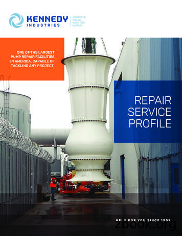
CRANE DEMING HAYWARD TYLER PYLES WILSON SNYDER . DURCO IMO SIMS ZOELLER TYPES OF PUMPS REPAIRED BY KENNEDY INDUSTRIES, INC.: Boiler Feed Pumps Piston Pumps Horizontal Split Case Pumps Submersible Pumps Vertical Turbine Pumps End Suction Pumps Circulating Pumps Sewage Pumps Vacuum Pumps Amine Pumps Slurry and Abrasive .
Oilgear engineers will be there, ready to help you with the education, field service, parts and repairs . Table of Contents Pvm Pumps page 3 PvWJ Pumps page page4 PvWh Pumps page page5 PvWW Pumps page 6 PvWc Pumps page page7 Pvg Pumps page 8 PvK Pumps page page9 Pvv Pumps page 10 PfBA Pumps page 11 PfBK Pumps 12 . 130 7.94 130,2 1500 103,4 .
HYDRAULIC BOTTLE JACKS 1 HYDRAULIC BOTTLE JACKS K12150 - 1850kg Hydraulic Bottle Jack K12151 - 4000kg Hydraulic Bottle Jack K12152 - 6000kg Hydraulic Bottle Jack K12153 - 10000kg Hydraulic Bottle Jack K12157 - 20000kg Hydraulic Bottle Jack K12158 - 10000kg Hydraulic Bottle Jack K12159 - 20000kg Hydraulic Bottle Jack ED1 / JUNE 19 Distributed by Kincrome Tools and Equipment www.kincrome.com.au
Mar 06, 2019 · Grundfos Efficiency Upgrade Guide. Table of Contents Page # Description: 3: Taco 00 Pumps: 5; Taco 1600 Pumps 7: Taco 1400/2400 Pumps 9: Taco 100 Pumps 11: Taco 00e Pumps 13: Taco Veridian Pumps 15: B&G 60 Pumps 17: B&G PL Pumps 19: B&G NRF Pumps 21: B&G 3-Piece P
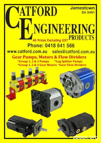
GEAR PUMPS MOTORS & FLOW DIVIDERS we www.catford.com.au email salescatford.com.au tel 0418 641 566 117 Vivoil Group 1 Pumps 120 Vivoil Group 2 Pumps 124 Vivoil Group 3 Pumps 130 Multiple Pump Nomenclature 134 Group 1 Pumps 136 Group 2 Pumps 137 Group 3 Pumps 139 Log Splitter Pumps 141 Vivoil Group 1 Gear Motors 142 Vivoil Group 2 Gear Motors 145 Vivoil Group 3 Gear Motors 148
Herrema Dairy - Fair Oaks, IN, USA Years ago, Herrema Dairy installed four GEA Futuro pumps. These pumps have been pumping every day for over 17 years, with minimal maintenance. "They can be carefree if you look after them," says Chris Peck. Herrema Dairy has now added six additional Futuro pumps for a total of ten. 2 · HYDRAULIC PISTON .
71h- hydraulic pumps / motors aluminium group 3 l 1 - l 2 72h- hydraulic gear flow dividers & hi - lo pumps m 1 - m 3 73h- hydraulic pumps o.e.m. & mini power packs n 1 74h- hydraulic pumps forklift o 1 - o 6 75h- hy


