Search a digitally controlled dcm flyback converter with a low
8 ni.com NI DCM-2316 Getting Started Guide What to Do Complete the following steps to connect power to the DCM. Ensure the DCM Starter Harness is connected as discussed in the Connecting the DCM Starter Harness section. Connect power supply leads terminated with properly rated ring terminals to the PDU
A representative flyback converter can be seen in Figure 3. Figure 3. A Simplified Schematic of a Flyback Converter CONTROL Vin T Q Ipri Vout D The power switch essentially places the primary inductance of the flyback transformer across the input voltage source when it is turned
winding and then decays back down in the secondary winding during the flyback interval. Thus, when designing the flyback transformer and assessing the losses, you must consider it more of an inductor than a transformer. Flyback operation Figure 2 shows the different operating phases of the fly
Analysis and Design of Multioutput Flyback Converter A study For A Lab Upgrade on the Flyback converter assignment at Chalmers Elteknik Master's thesis in Electric Power Engineering . The result of the transformer design shows that a new assignment that can demonstrate how magnetic core behaves can be introduced. Keywords: Flyback, Multi .
This manual is designed to allow you to setup and install your DL205 Data Communications Module (D2–DCM). This is the only manual you will need if you are using the D2–DCM as an extra general purpose communication port for your DL205 PLC system. If you plan on using the D2–DCM as a network master or sl
The DCM comes with an easy-to-use interface, simplifying the configuration of video processing functions across your video sources, and is supported by the Synamedia Video Network Service Manager (VSM), which enables you to easily provision DCM instances and even have service portability between the DCM appliance model and the virtualized DCM .
Model Number DCM-270BAH DCM-270BAH-OS AC Supply Voltage 115-120/60/1 Amperes 8.5 AMPS Design Pressure HI-427PSI LO-230PSI Refrigerant 404A 14.8 OZ. 7 B. Dimensions/Connections 1. DCM-270BAH Unit: mm [in.] 8 2. DCM-270BAH-OS Unit: mm [in.] 9 II. Installation and Operating Instructions WARNING
stage directly. Compared to a buck converter, the flyback converter may be the better choice. Figure 4 shows the typical circuit of a flyback converter. Figure 4. Flyback converter The auxiliary winding can be added to the transformer (T1) to provide bias for Q1. Unlike the buck converter, T1 provides isolation between Vin and Vout.
flyback converter are provided in Table I. Converter design and analysis In this section the high voltage bi-directional DC-DC converter, shown in Fig. 1 is discussed. High voltage unidirectional flyback converter for a normal resistive load is analyzed in [12] without considering all para
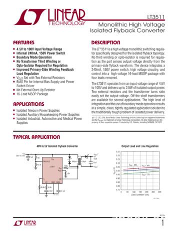
Isolated Flyback Converter The LT 3511 is a high voltage monolithic switching regula-tor specifically designed for the isolated flyback topology. No third winding or opto-isolator is required for regula-tion as the part senses output voltage directly from
GAIN DC/DC CONVERTERS A. Operation Principe and Soft-switching Behavior of Flyback-forward DC/DC Converters A flyback-forward high gain DC/DC converter is shown in Fig. 4 [16]-[18]. The main switches S1 and S2 work in the interleaved mode, and their control signals have a 180 degree phase shift. The active-clamp circuits are mainly composed
Design of Efficient Flyback Switching Power Supply Based on LM5021 HOU Xingang1, a,WANG Lei1, b,CHEN Heng1, c,and CHEN Jinglei1, d 1 Xijing U nivers ty ,' aS hx , C 7 10 23 a 707861498@qq.com, b774383203@qq.com, cchenhenrys@qq.com, d 843699667@qq.com Keywords: flyback switching power supply; LM5021; current-limiting circuit; transformer Abstract. The paper introduces the process of .


