PCS 7 SMART Getting Started - Part 1 (V9.0 With APL)
SIMATICProcess Control System PCS 7SMARTPCS 7 SMART Getting Started Part 1 (V9.0 with APL)Getting Started12/2017A5E42181435-AASecurity information1Preface2Requirements for GettingStarted3PCS 7 SMART overview4Initial work for the project5Creating CFCs6Creating SFCs7Compiling, downloading andtesting the charts8Configuring the operatorstation9Working in runtime10Performing the additional task11Starting and adapting thecolor gs project12
Legal informationWarning notice systemThis manual contains notices you have to observe in order to ensure your personal safety, as well as to preventdamage to property. The notices referring to your personal safety are highlighted in the manual by a safety alertsymbol, notices referring only to property damage have no safety alert symbol. These notices shown below aregraded according to the degree of danger.DANGERindicates that death or severe personal injury will result if proper precautions are not taken.WARNINGindicates that death or severe personal injury may result if proper precautions are not taken.CAUTIONindicates that minor personal injury can result if proper precautions are not taken.NOTICEindicates that property damage can result if proper precautions are not taken.If more than one degree of danger is present, the warning notice representing the highest degree of danger will beused. A notice warning of injury to persons with a safety alert symbol may also include a warning relating to propertydamage.Qualified PersonnelThe product/system described in this documentation may be operated only by personnel qualified for the specifictask in accordance with the relevant documentation, in particular its warning notices and safety instructions. Qualifiedpersonnel are those who, based on their training and experience, are capable of identifying risks and avoidingpotential hazards when working with these products/systems.Proper use of Siemens productsNote the following:WARNINGSiemens products may only be used for the applications described in the catalog and in the relevant technicaldocumentation. If products and components from other manufacturers are used, these must be recommended orapproved by Siemens. Proper transport, storage, installation, assembly, commissioning, operation andmaintenance are required to ensure that the products operate safely and without any problems. The permissibleambient conditions must be complied with. The information in the relevant documentation must be observed.TrademarksAll names identified by are registered trademarks of Siemens AG. The remaining trademarks in this publicationmay be trademarks whose use by third parties for their own purposes could violate the rights of the owner.Disclaimer of LiabilityWe have reviewed the contents of this publication to ensure consistency with the hardware and software described.Since variance cannot be precluded entirely, we cannot guarantee full consistency. However, the information inthis publication is reviewed regularly and any necessary corrections are included in subsequent editions.Siemens AGDivision Process Industries and DrivesPostfach 48 4890026 NÜRNBERGGERMANYA5E42181435-AA 11/2017 Subject to changeCopyright Siemens AG 2017.All rights reserved
Table of contents1Security information.92Preface.113Requirements for Getting Started.17453.1Hardware requirements for Getting Started - Part 1.173.2Software requirements for Getting Started - Part 1.183.3Required configuration for Getting Started - Part 1.19PCS 7 SMART overview.214.1PCS 7 SMART overview.214.2PCS 7 SMART inclusions.224.3Introduction to SIMATIC Manager.234.4Basic Structure of SIMATIC Manager.244.5Different views of SIMATIC Manager.254.64.6.1Procedure.26Opening SIMATIC Manager.26Initial work for the project.275.15.1.15.1.25.1.35.1.4Planning the project.27The "color gs" project.27Task list for Getting Started.28System configuration for the 'color gs' project.30Configuration tasks overview.315.25.2.15.2.25.2.2.1Preparational settings for the network.32Network and Interface settings.32Procedure.32Configuration console Creating the project.34"New Project" Wizard usage.34Background knowledge for the PCS 7 Wizard.34Procedure.36Creating the color gs Project.36Opening and Closing the "color gs" Project.39How to Work in the Various onfiguring the stations.41Configuration overview.41Procedure.42AS configuration.42Renaming the PC Station.44Configuring the PC station of the OS.45NetPro settings.47PCS 7 SMART Getting Started - Part 1 (V9.0 with APL)Getting Started, 12/2017, A5E42181435-AA3
Table of contents645.4.2.55.4.2.6Configuring and downloading the PC station of the OS.49Downloading the hardware configuration of the AS.505.55.5.15.5.25.5.35.5.45.5.55.5.6Working in the plant hierarchy.52Introduction to plant hierarchy.52Plant hierarchy settings.52Plant view structure.54Adapting default names.54Inserting additional hierarchy folders.57Checking the assignment of AS/OS to the plant hierarchy.585.65.6.1Current status.59Current state of your project.59Creating CFCs.616.1CFC Charts and the CFC .8Working with libraries.62CFC Charts and the master data library.62Storing objects in the master data library.62Working with the master data library.63Opening the libraries.64Storing blocks.65Storing process tag types.67Showing and hiding libraries.68Process to hide and show ological significance of the charts in the project.71Charts in "color gs" project.71Process-Related meaning of the "CFC SETP" CFC chart.71Process-Related meaning of the "CFC FC111" CFC chart.72Process-Related meaning of the "CFC LI111" CFC chart.72Process-Related meaning of the "CFC NP111" CFC chart.72Process-Related meaning of the "CFC NK11x" CFC chart.736.46.4.16.4.26.4.2.16.4.2.26.4.2.3CFCs in the Plant Hierarchy.74Working with CFC charts.74Procedure.74Renaming CFC charts in the Plant Hierarchy.74Inserting new CFC charts in the Plant Hierarchy.75Inserting the "Motor Lean" process tag type.766.56.5.1The current status.77Current status of your 6.86.6.96.6.10Working with the CFC Editor.78Introduction to the CFC Editor.78CFC Chart in the CFC Editor.78Catalog in the CFC Editor.79Configuration steps for CFC charts overview.80Opening the "CFC SETP" CFC chart.80Assignment of block parameters in CFC charts.81Inserting the blocks into the "CFC SETP".81Assigning parameters for the blocks in "CFC SETP".82Inserting the blocks into the "CFC FC111".84Assigning parameters for the blocks in the "CFC FC111".85PCS 7 SMART Getting Started - Part 1 (V9.0 with APL)Getting Started, 12/2017, A5E42181435-AA
Table of 176.6.186.6.19Inserting the blocks in the "CFC LI111".88Assigning parameters for the blocks in the "CFC LI111".89Assigning Parameters for blocks in the "CFC NP111".91Interconnection of blocks in the CFC charts.92Interconnecting blocks in the "CFC NP111".93Interconnecting blocks in the "CFC FC111".94Interconnecting blocks in the "CFC LI111".95Assigning parameters for the blocks in "Valve Lean".96Interconnecting the blocks in "Valve .7.2.5CFCs in the process object view.98Use of the Process Object View for valve control.98Procedure.98Defining Inputs/Outputs for the Process Object View.98Inserting the "Valve Lean" process tag type.100Adapting the parameters for "CFC NK11x".101Deleting Interconnections to addresses.103Selecting block icons.1046.86.8.1The current status.105Current status of your project.105Creating SFCs.1077.1Overview of Sequential Function Charts 2.87.2.97.2.107.2.11Working with the SFC Editor.108Introduction to the SFC Editor.108Important functions in the SFC Editor.108Properties of steps and transitions.109Overview of the configuration steps for SFC charts.110Moving an SFC chart.110Renaming the SFC chart.111Opening the "SFC RMT1" SFC Chart.112Technological structure of the sequential control system.112Creating the sequential control system in the SFC chart.113Renaming steps.115Renaming transitions.1177.37.3.17.3.27.3.37.3.47.3.5Setting parameters.119Assigning parameters to the steps of the SFC chart.119Parameters for the steps.122Assigning parameters to the transitions of the SFC chart.124Parameters for the transitions.125Optimizing the run sequence.1277.47.4.1The current status.128Current status of your project.128Compiling, downloading and testing the charts.1298.1Overview of compiling, downloading, and g and Downloading CFC and SFC charts.130Testing the program.133Testing the program in the SFC Editor.134PCS 7 SMART Getting Started - Part 1 (V9.0 with APL)Getting Started, 12/2017, A5E42181435-AA5
Table of contents91068.2.4Testing the program in the CFC Editor.1358.38.3.1The current status.137Current status of your project.137Configuring the operator station.1399.1Introduction to the OS project editor.1399.2Operator station in process mode.1409.3Configuration of the operator .49.4.2.5Working in the SIMATIC Manager.142Preparations in SIMATIC Manager.142Procedure.143Editing picture properties.143Deleting unnecessary pictures.144Creating block icons.145Compiling the OS.147Starting the PCS7 SMART OS.1509.59.5.19.5.29.5.3Working on the OS.151Structure of the OS - WinCC Explorer.151Function of process pictures.151Setting the OS activation for the g in general with the Graphics Designer.153Introduction to the Graphics Designer.153Opening a Process Picture.153Opening various toolbars.154Objects in the Graphics Designer.155Static objects.156Text fields.156Working with tag .69.7.79.7.89.7.99.7.109.7.11Creating the process picture.157Inserting pipes and a tank into the process picture.157Labeling the parts of the plant.160Step 1 - Inserting a text field.160Step 2 - Setting the text field.160Step3 - Duplicating the text field.161Current status of the process picture.163Adapting process pictures.163Connecting the raw material tank with the process value.164Step 3 - Adding explanatory text.167Step 4 - Configuring the setpoint default.168Completing the work.1699.89.8.1The current status.170Current status of your project.170Working in runtime.17110.110.1.110.1.2Planning the user interface.171Operator station in process mode.171User interface in process mode.17110.2Operator control and monitoring in process mode.173PCS 7 SMART Getting Started - Part 1 (V9.0 with APL)Getting Started, 12/2017, A5E42181435-AA
Table of 10.2.810.2.910.2.101112WinCC language settings.173Activating process mode.173Starting the process.174Stopping the process.177Controlling the process by means of the process picture.177Specifying the reactor.177Opening the faceplates.178Changing the setpoint.178Working with messages.182Process mode exit.184Performing the additional task.18511.1Introduction to the additional task.18511.2Copying the existing 'RMT1' part of the plant.18611.3Process mode preparation.18811.4Compile and download the changes.18911.5Adapting the OS configuration.19411.6Starting process mode.195Starting and adapting the color gs project.19712.1color gs dure.198Opening the color gs project.198Adapting the hardware for the color gs project.198Adapting the blocks for the color gs project.
SIMATIC Process Control System PCS 7 SMART PCS 7 SMART Getting Started - Part 1 (V9.0 with APL) Getting Started
F Footboard 1 PC G Drawer Suppt. Rail - 2 4 PCS H Side Rail 2 PCS I Bed Slat 2 PCS JF/Board Drawer Frame 1 PC KConcealed Panel 5 PCS L Drawer Suppt. Rail - 1 1 PC MSupport Leg 1 - 30 x 30 x 518mm 5 PCS NSupport Leg 2 - 30 x 30 x 95mm 1 PC OSupport Leg 3 - 30 x 30 x 107mm 1 PC P Bed Slat with marking 2 PCS Q Drawer - 1 4 PCS R Drawer - 2 2 PCS PAGE 1 OF 6 NODESCRIPTION SKETCH QTY
sashimi set with sushi rice party platter set b (37pcs) salmon set (18 pcs) 5 people party platter (82 pcs) nigiri roll set (13 pcs) omakase nigiri (5 pcs) tuna set (18 pcs) honi gunkan set (5 pcs) 3 roll choice combo (18 pcs) honi gunkan and roll set party platter set a (37 pcs) 18.95 49.95 19.95 96.95 19.95 24.95 24.95 32.95 .
Getting Started applies to the "PCS 7 Engineering Toolset V 6.0". Preface Process Control System PCS 7, Getting Started - Part 1 iv A5E00164244-01 Guide to the Manual Getting Started explains the individual steps required to create the "color_gs" project. You will find the most important background information required to
Shelf 4 pcs. K1. Fixed Shelf 1 pc. M. Door 1 pc. N. Door 1 pc. C. Side Panel 1 pc. E. Middle Panel 1 pc. J1. Fixed Shelf 2 pcs. K2. Shelf 2 pcs. L. Glass Door 4 pcs. Steel Plate Connector 2 pcs. Wood Screw for Steel Plate Connector 8 pcs. ( 1 extra) Dining Hutch(Cottage Oak) Door Pull Handle 2 pcs. Small Hex Wrench 1 pc. Arts & Crafts
Love Stretch Bracelet Min. 2 pcs #0151 Peace Cuff Bracelet Min. 2 pcs #2651 Peace Bracelets Min. 2 pcs #509 Bling Peace Bracelet Min. 2 pcs. #2657JT Black & Silver Peace Bracelet Min. 2 pcs. #9196 Peace Stretch Bracelet Min. 2 pcs. #2657BN Brown & Silver Peace Bracelet Min. 2 pcs. 2 Wear N
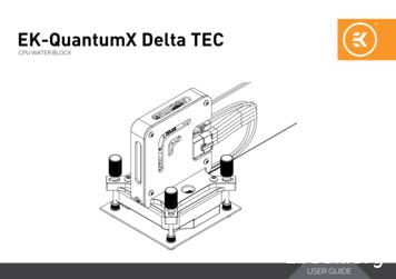
EK-QuantumX Delta TEC Water Block Coiled Spring (4 pcs) Big Backplate Sticker (1pcs) Backplate (1 pcs) M4 PVC Washers (4 pcs) Sticker (1 pcs) EK-Cable 5-Pin Motherboard (F) to Micro-USB (M) (1pcs) Screw (4 pcs) Thumb Nut (4 pcs) Thermal Grease (1 pcs) EK-QuantumX Delta TEC
LUMBER COMPANY. 1x4-16' S4S 120 pcs/unit 1x6-16' S4S 80 pcs/unit 1x8-16' S4S 60 pcs/unit 1x10-16' S4S 50 pcs/unit 1x12-16' S4S 40 pcs/unit 1x6-16' Nickel Gap 120 pcs/unit 1x8-16' Nickel Gap 90 pcs/unit Funch Lumber Cincinnati
Introduction Description logics (DLs) are a prominent family of logic-based formalisms for the representation of and reasoning about conceptual knowledge (Baader et al. 2003). In DLs, concepts are used to describe classes of individuals sharing common properties. For example, the following concept de-scribes the class of all parents with only happy children: Personu has-child.Personu has .


