Page 1 System Overview - 12 Outlet Monitoring System Single Section 1 .
Page 1System Overview - 12 Outlet Monitoring System1 PRODUCT(s), 1 Section(s)[not to scale]Single SectionRows 1-12Liquid Application Equipment Overview16CH Product Node Harness8-pin Node Connection- from Node1 toTerminator-Electronic ControlUnit (ECU)ECUTerminatorNODE #11st in series16CHProduct Node16CH NodeCapTo 12V powerQuad-sensor cables[not to scale]patent pendingElectronic Flowmeters (EFM), Electronics & Harnesses Parts ListManifold, 12 OutletsFLOWFrom PumpQuantityPART#DescriptionExtra Information111as req’das req’d20603-0020621-0020612-0020615-0020616-00ECU Base Kit16CH Node KIt16CH Node Harness CapExt. Harness [NODE to SNR]Ext. Harness [NODE to NODE]incl. 20’ battery harness, terminator, ECU, ECU antennaincl. 16CH Node, 16CH Node Harness, 4x Quad-sensor cableUsed to capping unused 16CH node harness connectors.6’ Extension Harness [6-pin], NODE to QUAD-SENSOR CABLE12’ Extension Harness [8-pin], NODE Harness to NODE HarnessManifold, Plumbing & Auxiliary Parts ListQuantityPART#DescriptionExtra -0020526-00205XX-00205XX-0021500-VXX4 Outlet EFM Manifold Kit3 Outlet EFM Manifold KitORS Manifold StrainerORS Manifold End-capORS TEE w/ 1/4” NPT-F*ORS Inlet FittingORS Outlet FittingORS Metering Orificeincl. 4-Outlet manifold, 4 EFM assembly kits (incl. jets), 4x Check Valveincl. 3-Outlet manifold, 3 EFM assembly kits (incl. jets), 3x Check ValveOne strainer per Manifold Feed.Two used per center-fed manifold.*1/4” NPT Port comes sealed; must be drilled out to be used.ORS Inlet must be selected from catalog by preference (up to 1”).ORS Outlet must be selected from catalog by preference.ORS metering orifice size must be selected by required flow rate.[Rear View]FLOWTo Outlet12x Electronic Flowmeters (EFM)One per outletEach EFM (36 total) has a sensor cable plugged intoit. When powered, each EFM sends signal through theProduct Node Harness, to Product Node, to ECU.From ECU, wireless transmits to an Android tablet, anddisplays flow rate and other information to user.Part No. 12Rev. 1Outlet EFM Plumbing Manifold AssemblyOverview, 1-productDec 17/19Item Description Flow Monitoring Manifold System, 12 Total OutletsORS Manifold Plumbing, 1 Section Layout (12 outlet/product)
Page 2Manifold Breakdown, 12 OutletsPRODUCT 1Manual ON/OFFCheck ValveWhen ‘ON’, acts like check valve.When ‘OFF’, turns off flow formaintenance/etc.Flowmeter Jetpatent pendingStabilizes the flow across the flowmeterpaddle wheel for more accurate andconsistent readingsColor coded to flow range.(Green/Red/Blue/Black)[Optional] ORS Strainer [not to scale]50 Mesh ORS Strainer AssemblyHousing Strainer CartridgeNEWORS Outlet/Inlet FittingsA variety of sizes and types of fittings can beused from the O-ring Seal (ORS) outlet family.From Hose Barbs, to threads, to quick-connecttube.Flowmeter Bodypatent pendingSensor is inserted into [rear side] housing.Relays pulse feedback to product node.ORS Metering Orifice [Optional*]If manifold is being used to meter liquid flow,use orifice. If metering orifice exists in systemelsewhere, ignore ORS metering orifice.ORS Tee [not to scale]Center-feeds a plumbing manifoldwith an ORS InletORS Manifolds [not to scale]O-ring seal manifolds are available in 1-4 outlet varieties.Common U-clip design connects to any ORS fittings.ORS End-Cap [not to scale]An end-cap is used toterminate any manifold end.Manifold, 12 OutletsFLOWPart No. EFM[Back View]No sensor cableRev. 1Dec 17/19Flow Monitoring Manifold System, 12 Total OutletsORS Manifold Plumbing, 1 Section Layout (12 outlet/product)Item DescriptionFLOWPlumbing Manifold, 12 Outlet
Page 38-pin NodeConnection- from Node 1 toTerminator-ECUTerminator! IMPORTANT! !- A terminator must be connectedto the last node in series’ 8-pinconnection -ECU Antenna(50’)! IMPORTANT! !- Product Nodes are labled by ECU,based on which node is connectedfirst/second/third/etc in series -Product Node 1Product Node 1 Harness8-pin NodeConnection- from ECU -Electronic Control Unit(ECU)STARTHERE12VPower20’ Battery Harness(included, not shown)16CH HarnessCap6-pin Quad-SensorCable Connections! Extension Harness are also available [not shown]12’ Node to Node Extension Harnesses [8-pin]6’ Node to Quad-Sensor Cable Extension Harnesses [6-pin]Part No. EFMPlumbing Manifold, Electronics Breakdown, Rev. 13 NODESDec 17/19Item Description Flow Monitoring Manifold System, 12 Total OutletsORS Manifold Plumbing, 1 Section Layout (12 outlet/product)
Page 4Sensor Connections Breakdown - 12 Outlet ManifoldPRODUCT 1: ROWS 1-12! IMPORTANT! !- Product Nodes are labled by ECU,based on which node is connectedfirst/second/third/etc in series -8-pin NodeConnection16CH Product Node Harness- from ECU -La8-pin NodeConnectionlqbeuaend-s- to Terminator-bcaQuad-SensorCableleshNwit! IMPORTANT! !- Quad-sensor cables have 4 sensors,with the molded label (1/2/3/4) designedby the marking on the base of the cable -rso16CH Product Nodeodabecleterlet1!B16CH Product NodeHarness Cover CapSince only 3 of 4 harnessconnections are being used byquad-sensor cables, we needto cap the unused harnessconnection off.! We will ensure to rememberthat this harness location ‘B’ isnot used, when entering sensorlocations into the APP’s sensorsetup screen.For example:NODE 1, DIV B, SNR 1 will NOT bea valid sensor location, as SNR 1-4is ‘capped’ off.[Rear View]4Each EFM (12 total) has a sensor cableplugged into it. When powered, eachEFM sends signal through the ProductNode Harness, to Product Node, to ECU.From ECU, wireless transmits to anAndroid tablet, and displays flow rateand other information to user.Quad-Sensor CableLabelsDEach EFM connected to a sensorcable can now be added to thepumbing manifold.C3AQuad-sensor Cableconnected to4 individual EFMs2PRO-TIP: Labeling Quad-Sensor CablesAWith a white marker,label each quad-sensorcable with A, B, C or D,based on which ProductNode Harness cable it isconnected to.Part No. EFMRev. 1Plumbing Manifold, 12 Outlet, SensorConnections Breakdown, PRODUCT 1, Row 1-12 Dec 17/19Item Description Flow Monitoring Manifold System, 12 Total OutletsORS Manifold Plumbing, 1 Section Layout (12 outlet/product)
Page 5NOTE: The following may look different depending onapp version being used, but in essence, will be the same.Follow the manual for the most up-to-date reflection of the app.How To Label Sensors For Entry Into APP PRODUCT 1, Outlets 1-12Using NODE 1, which allows you toAfter completely setting up the ECU Settings Screen, enter the Sensor Setup Screenenter each respective product sensor in it’s correct position, relative to the ECU.While sensors do not have to be connected in consecutive order as laid out on your application implement, they dohave to be entered accurately within the app to reference properly on the display.The below example screen is only ONE depiction of how to set a screen up. For convenience, you can customizethe layout of the outlets on up to 10 ‘section’ pages.For simplicity, for a 12 outlet implement with 3 products, it will show on one screen, as 12 rows and 3 products.“Section 1”: 12 OutletsWe have to ‘label’ a sensor, basedon its location. The label is derivedfrom its:PRODUCT NODE#: NODE 1! IMPORTANT! !- Product Nodes are labled by ECU,based on which node is connectedfirst/second/third/etc in series -QUAD-SENSOR CABLEDIVIDER [DIV] LABEL:A/B/C/D! IMPORTANT! !- Quad-sensor divider labels arelabeled on the node harness itself,labeled with either an A, B, C, or D -SENSOR CABLELABEL:1/2/3/4! IMPORTANT! !- Sensor cable labels are molded (orlabeled) on the actual quad-sensorcable, with either a 1/2/3/4. Ensureyou refer the sensor label correctly. -How to Read the Sensor Location (Eg. Location 1A4)Physical RowDescriptionThis is manually addedto depict which row thisis on the implement.For example, if asection begins at row‘17’, this cell can beentered as “17”, etc.In this example, itbegan at ROW 1.[NODE]PRODUCT NODE #If the sensor is connectedthrough the PRODUCT NODE#2 harness, ensure underNODE, it is listed as ‘2’.Ensure a sensor’s [NODE]corresponds with its correctNODE #.In this example, sensors 1-12for Prod 1, began at NODE 1.[DIV]QUAD-SENSOR CABLEHARNESS LABELSelect A / B / C / D based onthe corresponding node harnesscable that a quad-sensor cable isattached to.In our example, the first rows areattached to DIV C, as shown inthe system overviews.[SNR]SENSOR CABLE LABELDepending on the sensor cable’snumber (1/2/3/4) that is moldedinto the quad-sensor cablehousing, enter the sensor numberwith the corresponding outlet.In our example, SNR 1 is the firstrow of product on the implement.After entering your sensor locations into the app, as you’d like them laid outon pages 1-10, you can verify each line of the example as follows:Outlet 12 is connected to SENSOR 4 or [SNR 4] on the quad-sensorcable, on the Node Harness Cable ‘A’ or [DIV A], which is connected toProduct Node 1 or [NODE 1].Part No. EFMRev. 1Plumbing Manifold, 12 Outlet, SensorConnections Breakdown, Product 1, Outlet 1-12 Dec 17/19Item Description Flow Monitoring Manifold System, 12 Total OutletsORS Manifold Plumbing, 1 Section Layout (12 outlet/product)
Liquid Application Equipment Overview Quantity PART# Description Extra Information 1 20603-00 ECU Base Kit incl. 20' battery harness, terminator, ECU, ECU antenna 1 20621-00 16CH Node KIt incl. 16CH Node, 16CH Node Harness, 4x Quad-sensor cable 1 20612-00 16CH Node Harness Cap Used to capping unused 16CH node harness connectors.
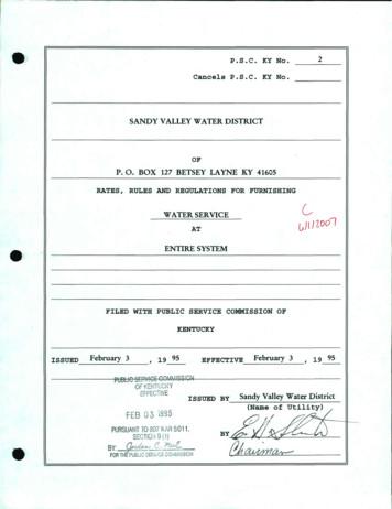
ef-fec1we issued by sandy valley water district ,-eb ri 7 '. ovh :- vi) hjj\j (name by -@- index page 1. page 2. page 3. page 4. page 5. page 6. page 7. page 8. page 9. page 10. page 1 1. page 12. page 13. page 14. page 15. page 16. page 17. page 18. page 19. page 20. .
The Lenape / English Dictionary Table of Contents A page 2 B page 10 C page 10 D page 11 E page 11 F no Lenape words that begin with F G page 14 H page 19 I page 20 J page 20 K page 21 L page 24 M page 28 N page 36 O page 43 P page 43 Q page 51 R no Lenape words that begin with R S page 51 T
Page 2 Econo-Form Overview Page 3 General Assembly Page 4 Panels Page 5 Channels & Fillers Page 6 Tube & Fittings Page 8 Corners Page 9 Push-Pull Props Page 10 Flex-Forms Page 11 Ties - Ferrule Type Page 12 Ties - Form Type Page 13 Ties - Dywidag Type Page 14 Ties - Water-Bar Type Page 15 Ties - Coil Type Page 17 Extractors Page 18 Climbing
Cahier pédagogique À deux roues, la vie! DynamO Théâtre 2 page 3 page 3 page 3 page 4 page 4 page 5 page 5 page 5 page 6 page 7 page 8 page 9 page 10 page 11 page 12 page 12
ÌSprue Bushing MSB-A3530 Page 18 Page 18 Page 18 Page 19 Page 19 Page 19 Page 20 Page 20 Page 20 Page 21 Page 21 Page 21 Page 22 Page 22 Page 22 Page 23 MSB-B3030 MSB-C2520 MSB-D3030 MSB-E2520 MSB-F1530 MSB-G3520 MSB-H3530 . HOT CHAMBER S L GP GB GPO EP C SB SP CL ML MAIN PRODUCTS ITEM
Trouble Shooting Safety Information INS-FM-30 . Remoter Control Operation Page 2 4 Page 5 6 Page 7 Page 8 Page 9 Page 10 Page 10 Page 11 Page 12 Page 13 Page 14 Page 15 Page 16 18 Page 17 1 Warranty Service History Dealer Contact Information Page 20 .
Page 9 TM 886 TM 817 Page 9 TM 877 Page 9 TM 995 Page 9 TM 916 TM 937 TM 972 Page 12 TM 1300 — 1-3/4" Page 8 TM 1305 — 1-3/8" Rb3 Page 16 Rb4 CORneR b OCkS Page 19 wIndOw STOOl Page 7 R 6 Page 16 InTeRIOR JaMbS exTeRIOR JaMbS Page 18 TM 400 Page 8, 12 RadIuS CORneRS Page 19 PyRaMId CORneR blOCkS Page 19 TM 413 Page 12 TM
Set Manual Control Output and Brake Light Switches Initial Setup Test Drive & Adjustment Bench Test Troubleshooting Guide page 2 page 2 page 3 page 3 page 4 page 5 page 6 page 7 page 7 page 8 page 11 page 11 page 12 page 12 page 14 1. Drill 2. Drill bit, 5/16" 3. Phillips screwdriver 4. Pry tool TABLE OF CONTENTS CONTROLS & COMPONENTS TOOLS .


