105 Series Technical Fischer Connectors SA Multipole Low .
TechnicalSpecifications105 SeriesFischer Connectors SASaint-Prex, SwitzerlandPhone 41 21 800 95 95Fax 41 21 800 39 chMultipole Low VoltageProduct range covered:S / SC / SA / SV / SOV / SS / SSC / WSO / SF / SFE / SFU / SFPE / SFPU / D / DB / DBP / DBPC / DG / DGPDEE / DEU / DBEE / DBEU / DBPE / DBPU / DBPLE / DBPLU / K / KE / KS / KSE / DKBE / WDEProduct Benefits Up to a maximum of 27 contacts Unsealed (IP50), waterproof (IP68) or hermeticallysealed 3 keying-codes Reverse contact variants Standard matt silver chrome or non-reflective mattblack chrome finish Full range of accessories including bend reliefs andsealing caps available Scoop-proof (IEC 60512-1-4)Representative image ofstandard S and D bodiesPagesEnvironmental & Mechanical Data . 2Material & Surface Treatments . 2Electrical Data . 2Contact Configurations . 3Tooling . 5Information provided herein is believed to be accurate at time ofpublishing. Fischer Connectors reserves the right to make modifications on products for continuous improvement without prior notice. Fischer Connectors SA / All rights reservedThis document is the proprietary of Fischer Connectors SA.All communications to third parties or the reproduction in any form, even partial, are prohibited without our written consent.Document No. 600.00.458Rev : 2.3Date : 03 Oct. 12Established by : SKEApproved by : SRHPage 1 of 5
105 SeriesMultipole Low VoltageEnvironmental & Mechanical DataCharacteristicSealing PerformanceOperating Temperature Range(mated)IP50Plugs with(mated)General Purpose Sealed Clamps(1)IP68: 2 m submersion for 24 hoursIP69K (2)Receptacles “U” Body StyleIP68: 2 m submersion for 24 hoursReceptacles “E” Body StyleHermetic: Tested: 10-8 mbar l/sec.IP69K (2)Unsealed ConnectorsPlugs UsingGeneral Purpose Sealed Clamps-65 C to 200 CReceptacles “U” Body Style-50 C to 200 C(3)Receptacles “E” Body Style-50 C to 150 C(3)IEC 60529IEC 60068-2-17 Test Qk,Method 3-65 C to 130 CCorrosion ResistanceIEC 60512-6-11 i jIEC 60068-2-14-NbIEC 60068-2-11 Test KaMIL-STD-202 Method 101Condition ASalt mist, 96 hours, 5% salt solution, 35 C10’000 mating cyclesIEC 60512-5-9aEIA-364-0910 to 2000 Hz, 1.5 mm or 15 g, 12 sweep cyclesper axis, 20 minutes per 10-2000-10 Hz sweepcycle, no discontinuity 1 usMIL-STD-202 Method 204Condition BEnduranceVibrationRadiation ResistanceStandardValueProduct TypeUnsealed Connectors(4)Unsealed ConnectorsPEEK:107 Gy ( 109 Rads)Sealed ReceptaclesViton O-rings:105 Gy ( 107 Rads)(1) The sealing performance can be affected by the long term quality of the cable.(2) Dust tight, protected against the effects of high-pressure liquids. The test requirements for IP69K exist only in DIN 40050-9, the German version of IEC 60529.Operating temperature of Viton O-ring: -20 C to 200 C. Min mating temperature of 0 C.(3) With Viton O-ring (standard) in receptacle interface:With EPDM O-ring (Low temp) on request in receptacle interface: Operating temperature of EPDM O-ring: -50 C to 160 C. Min mating temperature of -20 C.(4) For information only. Not tested by Fischer Connectors.Material & Surface TreatmentsFinishMaterialMetal meover NickelSAE-AMS 2460Body ShellBrassCuZn39Pb3CW614NUNS C 38500Cable Clamps, Nutsand other Inner PartsBrassCuZn39Pb3CW614NUNS C 38500NickelSAE-AMS-QQ-N-290SAE-AMS 2404- Male (solder)BrassCuZn39Pb3- Female, - Male (crimp)BronzeCuSn4Zn4Pb4CW614NUNS C 38500CW456KASTM B 139, UNS C 544001 µm Goldover NickelMIL-DTL-45204D Type IASTM B488ContactsInsulator and SealingInternational SymbolFlammabilityStandardInsulatorPEEKUL 94 V-0MIL-P-46183Interface O-rings(Receptacles)Viton EPDMUL 94 V-0UL 94 HB SAE-AMS 7276Sealant Material(Receptacles)- IP68- HermeticCable Sealing(Plugs)- IP68Silicon compoundEpoxy compoundTPE-SUL 94 V-0UL 94 HBUL 94 HBOur products are RoHS compliant and conform with the EC Directive 2002/95/ECElectrical DataCharacteristicContact Resistanceover 10’000 Mating CyclesShell ResistanceInsulation ResistanceShielding EffectivenessDocument No. 600.00.458Rev : 2.3Contact SizeTypical ValuesStandardØ0.7 mmØ0.9 mmØ1.3 mmØ1.6 mmØ2.0 mmØ2.3 mmØ3.0 mm5 mΩ4 mΩ2.5 mΩ2.5 mΩ2.5 mΩ2.5 mΩ1.5 mΩIEC 60512-2-1-2aIEC 60512-2-2-2b10 mΩIEC 60512-2-6-2f 1010 ΩIEC 60512-3-1-3a, Method C 60 dB up to 1GHzIEC 60512-23-3Page 2 of 5
105 SeriesMultipole Low VoltageContact Diameter[mm]CurrentRating[A]RatedVoltage r.m.s.[V]Insertion/ExtractionForce (typ.) [N]CrimpContactsIEC 60512-5-2-5bIEC 60664-1IEC 60512-7-13a, MIL-STD-1344(3)(4)UnsealedSealed-26 630 30 45-30 400 35 55-23 400 30 45-20 320 35 55-25 320 35 55 320 35 55 250 40 60 320 40 60 320 40 60Wire SizeSolder (1)Contacts(2)(5)Max Ø2.03 AWG13 [1]AWG14 [7/22]Max Ø3.13 mmAWG9 [1]AWG10 [105/30]Max Ø2.03 mmAWG13 [1]AWG14 [7/22]Max Ø2.03 mmAWG13 [1]AWG14 [7/22]Max Ø2.03 mm1105A054Z7AWG13 [1]AWG14 [7/22]Max Ø1.18 mm61052.01.3AWG17 [1]AWG18 [16/30]-7.0-10-18.5Max Ø1.18 mmA067Z81.3AWG17 [1]AWG18 [16/30]Max Ø2.48 mm2105A 1242.38AWG11 [1]AWG12 [7/20]Max Ø1.18 mm61.312.0AWG17 [1]AWG18 [16/30]-7.5-25Max Ø2.03 mm105A101Z9Max Ø1.18 mm8105A062ZAWG13 [1]AWG14 [7/22]1.3AWG17 [1]AWG18 [16/30]Max Ø1.18 mm101.3AWG17 [1]AWG18 [16/30]-Max 1.18 mmMin 0.58 mm5.09.0AWG18-24(1)Stranding values in brackets.(2)Exceptionally for a given AWG, the diameter of some stranded conductor designs could be larger than the holediameter of the barrel. Trials may be required.(3)Recommended max. operating current per contact at 40 C temperature rise.(4)Recommended operating voltage at sea level.This rated voltage is a general purpose guideline where no other electrical safety standard applies. In case otherstandards rule a specific use of the connector, then the application specific safety criteria shall be considered first.This must be evaluated in the frame of equipment engineering.In case other calculation methods are preferred, please refer to general catalogue for test voltage data.(5)Values may vary strongly depending on environmental conditions, ageing, finish or type of seal.Document No. 600.00.458Rev : 2.3Page 3 of 5
105 SeriesMultipole Low VoltageContact Configurations eter[mm]CurrentRating[A]RatedVoltage r.m.s.[V]Insertion/ExtractionForce (typ.) [N]CrimpContactsIEC 60512-5-2-5bIEC 60664-1IEC 60512-7-13a, MIL-STD-1344(3)(4)UnsealedSealed-8.0 250 45 60-14 320 40 60 320 40 60 250 40 60 250 45 654.5 200 45 603.5 250 55 703.0 250 60 75Wire SizeSolder (1)Contacts(2)(5)Max Ø1.18 mmA069Z121.3AWG17 [1]AWG18 [16/30]Max Ø1.18 mm3105A104Z13A 127AWG17 [1]AWG18 [16/30]Max Ø0.79 mm(6)1051.3100.731.3AWG21 [1]AWG22 [7/30]--Max 1.18 mmMin 0.58 mm1.014AWG18-2413100.7-Max 0.62 mmMin 0.38 mm1.0AWG24-28105Max Ø0.79 mmA058Z150.9AWG21 [1]AWG22 [7/30]Max 0.83 mmMin 0.48 mm5.3AWG22-26Max Ø1.86 mm4105A110Z1.616-14Max Ø0.79 mm120.7AWG21 [1]AWG22 [7/30]Max Ø0.79 mmA038Z18105A093Z240.7105A102Z270.7105AWG13 [1]AWG14 [7/22]0.9AWG21 [1]AWG22 [7/30]-Max 0.83 mmMin 0.48 mm1.0AWG22-26Max Ø0.79 mmAWG21 [1]AWG22 [7/30]Max Ø0.79 mmAWG21 [1]AWG22 [7/30]-Max 0.62 mmMin 0.38 mmAWG24-28(1)Stranding values in brackets.(2)Exceptionally for a given AWG, the diameter of some stranded conductor designs could be larger than the holediameter of the barrel. Trials may be required.(3)Recommended max. operating current per contact at 40 C temperature rise.(4)Recommended operating voltage at sea level.This rated voltage is a general purpose guideline where no other electrical safety standard applies. In case otherstandards rule a specific use of the connector, then the application specific safety criteria shall be considered first.This must be evaluated in the frame of equipment engineering.In case other calculation methods are preferred, please refer to general catalogue for test voltage data.(5)Values may vary strongly depending on environmental conditions, ageing, finish or type of seal.(6)Reverse polarityDocument No. 600.00.458Rev : 2.3Page 4 of 5
105 SeriesMultipole Low VoltageToolingContactGenderDesignationCrimp Tool(1)Crimp Positioner(1)Size [mm]Part .3TX00.312Ø0.7TX00.210Ø0.9TX00.211MaleContact Insertion ToolContact Extraction ToolOpen-End SpannerExtra ThinNut Driver with T-Handle andHex Drive for Decorative Slotted 01922TX00.02224TX00.02425TX00.025M 18 x 1TP00.011M 20 x 1TP00.005(1) For detailed crimping instructions, log on to our online technical library at www.fischerconnectors.com/technicalDocument No. 600.00.458Rev : 2.3Page 5 of 5
IEC 60664 1 (4) Current Rating [A] IEC 60512 -5 2 5b (3) 105 A Z 069 12 45 Max Ø1.18 mm AWG17 [1] AWG18 [16/30] 1.3-8.0 250 60 105 - A Z 093 24 0.7 55 70 105 18 45 A Z 038 0.9 Max Ø0.79 mm AWG21 [1] AWG22 [7/30] Max 0.83 mm Min 0.48 mm AWG22-26 60 Max Ø0.79 mm AWG21 [1] AWG
SSMA Connectors End Launch Connectors 2.40 mm Connectors Adapters 2.92 mm Connectors TNC Connectors Super SMA Connectors N Series Connectors 54 End Launch Connectors Dimensions End Launch Connector Dimensions Field Replaceable .375" Square Flange Connectors are Available in Male or Female Configurations. Standard Profile Connectors Low .
SSMA Connectors End Launch Connectors 2.40 mm Connectors Adapters 2.92 mm Connectors TNC Connectors Super SMA Connectors N Series Connectors 54 End Launch Connectors Dimensions End Launch Connector Dimensions Field Replaceable .375" Square Flange Connectors are Available in Male or Female Configurations. Standard Profile Connectors Low .
fischer service engineers GERMANY fischerwerke GmbH & Co. KG Klaus-Fischer-Straße 1 72178 Waldachtal Germany Phone 49 (0)74 43 12 - 45 53 act@fischer.de · www.fischer.de Further information and approvals can be downloaded from the homepage of fischer: www.fischer.de ACT Service Argentina fischer Argentina S.A. Armenia 3044 1605 Munro .
Baermann Complete Method - Part 3 Fischer 13.95 Bettony-Baermann Method for Clarinet Fischer 15.95 Feldstein/Clark The Yamaha Advantage Fischer 6.95 Klose Celebrated Method - Complete Fischer 25.95 Klose Daily Exercises Fischer 6.95 Klose Scales and Exercises Fischer 6.95 Klose My First Klose Fischer 6.95 Klose-Prescott First and Second Year .
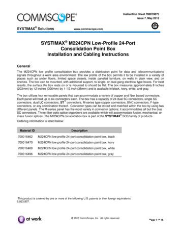
Each panel will hold up to six connectors each. The box has a capacity of 24 dual SC connectors, single SC connectors, dual LC connectors, ST connectors, M-series type copper connectors, BNC connectors, F-type connectors, or any combination thereof. Connector types can be mixed and matched within the box by using two different panels.
Test. 5. One Is Known As Volumetric Karl Fischer Titration. The Other Method Is Known As Coulometric Karl Fischer Titration. KF METHODS Volumetric Titration Coulometric . PRINCIPLE OF WORKING 1. The Principle Of Karl Fischer . Amount Of Karl Fischer Reagent To Reach The Characteristic Endpoint. 2. Weight Accurately 150 - 350 Mg Of Sodium .
SMP Series page 73 FAKRA Connectors page 77 BNC Series page 79 TNC Series page 108 N Series page 133 7/16 Series page 149 UHF/MINI-UHF Series page 159 F Series page 167 Twin Series page 175 D-sub Series page 179 FME Series page 181 1.0/2.3 Series page 183 1.6/5.6 Series page 189 Filtered Series page 197
Zecharia Sitchin these aliens had been coming here for a long time and even brought civilization to Planet Earth. Civilization? No, barbarism, cursed Roland. Today, with millions of claimed UFO sightings encounters with aliens alleged kidnappings investigators everywhere were coming right out and calling it an epidemic.


