V46 And V47 - Johnson Controls
V46 and V47Repair Parts and Service InstructionsPart No. 24-8414-12, Rev. DCode No. LIT-121695Issued August 2018Refer to the QuickLIT website for the most up-to-date version of this document.ApplicationsThe V46 pressure-actuated and V47 temperature-actuated water-regulating valves are used for water-cooledcondensers, bypass service on refrigeration systems, engine cooling, and various industrial applications.IMPORTANT: The V46 and V47 valves are intended to control liquid flow under normal operating conditions.Where failure or malfunction of the V46 and V47 valves could lead to personal injury or property damage to thecontrolled equipment or other property, additional precautions must be designed into the control system.Incorporate and maintain other devices, such as supervisory or alarm systems or safety or limit controls,intended to warn of or protect against failure or malfunction of the V46 and V47 valves.Installation GuidelinesFollow these guidelines to install the V46 and V47 valves. Flush liquid lines to remove filings, chips, and other foreign matter before connecting to the valve. Make liquid line connections so the flow through the valve is in the direction of the arrow on the body casting. Make sure that the bulb and capillary do not rub against any metal obstruction that can wear and damage theelement. Tighten the connector and seal, if furnished with the closed tank connector by tightening the small gland nut onheavy tubing near the bulb. Avoid mounting the valve where the bulb might be partly above operating liquid level or surrounded by an airpocket. Mount the valve vertically with the bellows facing downward.This product is made of a copper alloy, which contains lead. The product is therefore not to be used on drinkingwater.Risk of Environmental DamageAvoid sharp bends in the capillary tubes. Sharp bends can weaken or kink capillary tubes, which may result inrefrigerant leaks or restrictions of flow.V46 and V47 Repair Parts and Service Instructions1
AdjustmentsTo raise the valve opening point on direct-acting valves, turn the adjusting screw counterclockwise. To lower thevalve opening point, turn the range adjusting screw clockwise. See Figure 2. The closing point of the valve is notadjustable. Pressure-actuated valves close approximately 3 to 7 psi (21 to 48 kPa) below the opening point, andtemperature-actuated valves close approximately 3 to 5 F (1.7 to 2.8 C) below the opening point.If the compressor operates in high ambient temperatures, head pressures may remain high enough during offcycles to prevent the valve from closing completely. In such instances, the opening point of the valve should beraised just enough to cause the valve to close during compressor standby periods. The opening of the valve raisesthe throttling point.The all-range pressure-actuated valve settings can be adjusted for both low pressure refrigerant ranges of R-134aand higher pressure refrigerant ranges ofR-22 (R-502).Manual FlushingTo clear any sediment that may accumulate, valves may be manually flushed by inserting screwdrivers under bothsides of the main spring and lifting upwards to flush the valve. Manual flushing does not affect valve adjustments.Figure 1:Manual FlushingInspection and ServiceTo inspect and replace internal parts, follow the procedures in this section.After long periods of operation, the valve seat and rubber disc may become worn, pitted, or wiredrawn, preventingthe valve from completely closing off, allowing leakage through the valve in the closed position, when the pressureand temperature is below the setpoint.Shut off the liquid supply and relieve pressure in the line before servicing the valve. Contents of liquid lines couldbe under pressure and the release of liquid under pressure may cause severe personal injury.V46 and V47 Repair Parts and Service Instructions2
No te : Parts supplied in the renewal kit replace both V46 and V47 Series valve assemblies.AssemblyFigure 2:Valve ComponentsServicing V46 and V47 2 in. and 2-1/2 in. ValveIMPORTANT: To decrease the pressure in the sensing element on the V47 valves, cool the bulb by submergingit in ice water. Do not remove the bulb from the ice water until the element is ready to be reinstalled. Otherwise,the pressure increases in the sensing element, resulting in a valve that is hard to reassemble.Figure 3:V46 and V47, 2 in. and 2-1/2 in.V46 and V47 Repair Parts and Service Instructions3
Risk of Personal Injury.Protect eyes. Do not remove the two screws on the sides of the spring housing. Disassembly can cause acompressed spring to fly out and may result in serious eye injuries, blindness, or other severe injury.1. Decrease the compression on the main spring by turning the range adjusting screw clockwise until it stops.Using excessive force to turn the screw beyond the stop point strips the thread.2. Remove the four screws holding the spring housing and remove the entire housing assembly. See Figure 2.3. Remove the valve assembly screw (Figure 3).4. Remove the guide post and old diaphragms (Figure 3).5. Remove the sensing element and the diaphragms between it and the valve body (Figure 3).6. Pull the disc, disc retainer, and extension sleeve assembly from the valve (Figure 3).7. Remove the old valve seat and replace it with the new valve seat (Figure 3). (A seat wrench is not provided for2 and 2-1/2 in. valves. Use 1-1/2 and 1-15/16 in. hex stock, respectively.)8. Replace the three diaphragms between the sensing element and valve body (Figure 4).9. Replace the guide plate gasket and bellows sealing ring (Figure 4).10. Assemble the sensing element to the valve body with the bellows push rod, new diaphragms, guide plategasket, and bellows sealing ring in place.11. Assemble the new disc, disc retainer, and extension sleeve.a. Apply a small amount of grease to the grooves on the bottom of the new extension sleeve and the top ofthe new disc retainer. Place oneO-ring into each groove.b. Place the subassembly into the valve.12. Place two new diaphragms on the spring housing end of the valve body.13. Screw the valve assembly screw through the guide post and into the bellows push rod (Figure 3).14. Place the spring housing assembly over the guide post and secure in place with the four housing screws.15. Adjust the valve to desired opening point. Then manually flush the valve. See the Manual Flushing section.V46 and V47 Repair Parts and Service Instructions4
16. Before leaving the installation, run the system through at least one complete operating cycle to be sure thevalve is operating correctly.Push Rodfor pressureGasketFigure 4: Guide Plate Gasket andBellows Sealing Ring IdentificationV46 and V47 Repair Parts and Service Instructions5
Servicing V46 and V47 3/8 in. through 1-1/2 in. ValvesIMPORTANT: To decrease the pressure in the sensing element on the V47 valve, cool the bulb by submergingit in ice water. Do not remove the bulb from the ice water until the element is ready to be reinstalled. Otherwise,the pressure increases in the sensing element, resulting in a valve that is hard to reassemble.ISO-loss WasherPostDisc StudDisc CupValve DiscGuide Plate GasketPush RodFigure 5: V46 and V47 3/8 in.through 1-1/2 in. ValvesRisk of Personal Injury.Protect eyes. Do not remove the two screws on the sides of the spring housing. Disassembly can cause acompressed spring to fly out and may result in serious eye injuries, blindness, or other severe injury.1. Decrease the compression on the main spring by turning the range adjusting screw clockwise until it stops.Using excessive force to turn the screw beyond the stop point strips the thread.2. Remove the four screws holding the spring housing and remove the entire housing assembly. See Figure 2.3. To improve the performance on 3/8 in. direct-acting valves, install the ISO-loss washer that is supplied with the3/8 in. valve repair kit as follows:Note: Reverse-acting 3/8 in. valves do not require the ISO-loss washer.a. Slightly squeeze the spring housing assembly to remove the spring housing.b. Remove the range adjusting screw, spring, and valve spring guide (Figure 6).c.Clean off any excess grease on the valve spring guide.d. Place the new ISO-loss washer over the guide plate.e. Replace the valve spring guide, spring, range, adjusting screw, and spring housing.V46 and V47 Repair Parts and Service Instructions6
ISO-lossWasherFigure 6:ISO-loss Washer4. Remove the seat guide post (Figure 5).5. Remove the rubber diaphragms (Figure 5).6. Turn the disc stud counterclockwise to remove the valve stem assembly (Figure 5).7. Remove the sensing element, bellows push rod, and diaphragms. See Figure 8.8. Using the seat wrench supplied with the kit, remove the old valve seat and replace it with the new valve seat(Figure 5).9. Assemble the new valve stem, disc, disc cup, and disc stud, and place into the valve body (Figure 5).10. On 1 in. and larger pressure valves and all temperature valves, replace the guide plate gasket and bellowssealing ring (Figure 8).11. If servicing a V47 or V46 valve other than low flow, place new diaphragms on the sensing element end of thevalve stem assembly. Use two diaphragms on 3/8 in., 1/2 in., and 3/4 in. valves and three diaphragms on 1 in.and larger valves. Screw the diaphragm into place with the bellows push rod. Attach the sensing element to thevalve body. See Figure 5.V46 and V47 Repair Parts and Service Instructions7
12. If servicing a low flow valve, place the stem washer and new diaphragms on the sensing element end of thevalve stem assembly. Use two diaphragms on 3/8 in., 1/2 in., and 3/4 in. valves and three diaphragms on 1 in.and larger valves. Screw the diaphragm into place with the bellows push rod. Attach the sensing element to thevalve body. See Figure 7.ISO-loss WasherPostDisc StudDisc CupValve DiscGuide Plate GasketPush RodFigure 7:Low Flow Valves13. Place two new diaphragms on the spring housing side of the valve body. Screw into place with the seat guidepost (Figure 7).14. Place the spring housing assembly over the seat guide post and secure in place with the four housing screws.15. Adjust the valve to desired opening point. Then manually flush the valve. See the Manual Flushing section.V46 and V47 Repair Parts and Service Instructions8
16. Before leaving the installation, run the system through at least one complete operating cycle to be sure thevalve is operating correctly.Renewal KitsPush Rodfor pressureGasketFigure 8: Guide Plate Gasket andBellows Sealing Ring IdentificationTable 1: Renew Kits (Part 1 of 2)Individual PartDescriptionCommercial Type: V46A, V46D, V47A, V47NSeat Guide Post111111Maritime andNavy Type: V46B, V46C1111DiaphragmKits forAll Types1Disc Stud11111111111Disc Cup (Retainer)11111111111Valve Disc11111111111111Valve Seat11111111111111Valve Stem111111111111Rubber Diaphragm4444555544455555Guide Plate Gasket1111111111111111Bellows Sealing Ring1111111111111111Valve Assembly Screw111Guide Post111Valve Disc Retainer111V46 and V47 Repair Parts and Service Instructions9
Table 1: Renew Kits (Part 2 of 2)Extension SleeveSeat Wrench111Sensing Element1112.111111111O-ring Seals1.1Contact Application Engineering at (414)-524-5535Stem WasherISO-loss Washer211223/8, 1/2, and 3/4 in. valves require two diaphragms on the spring end and two diaphragms on the sensing element end. Onethrough 2-1/2 in. valves require two diaphragms on the spring end and three diaphragms on the sensing element end.Reverse acting 3/8 in. valves do not require an ISO-loss washer.European Single Point of Contact:NA/SA Single Point of Contact:APAC Single Point of Contact:JOHNSON CONTROLSWESTENDHOF 345143 ESSENGERMANYJOHNSON CONTROLS507 E MICHIGAN STMILWAUKEE WI 53202USAJOHNSON CONTROLSC/O CONTROLS PRODUCT MANAGEMENTNO. 22 BLOCK D NEW DISTRICTWUXI JIANGSU PROVINCE 214142CHINAwww.penncontrols.com Johnson Controls and PENN are registered trademarks of Johnson Controls in theUnited States of America and/or other countries. All other trademarks used herein are the propertyof their respective owners. Copyright 2018 by Johnson Controls. All rights reserved.V46 and V47 Repair Parts and Service Instructions10
V46 and V47 Repair Parts and Service Instructions 3 Note: Parts supplied in the renewal kit replace both V46 and V47 Series valve assemblies. Servicing V46 and V47 2 in. and 2-1/2 in. Valve IMPORTANT: To decrease the pressure in the sensing element on the V47 valves, cool the bulb by submerging it in ice water. Do not remove the bulb from th
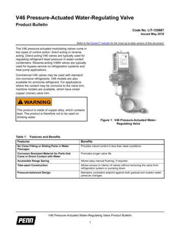
V46 Pressure-Actuated Water-Regulating Valve Product Bulletin The V46 pressure-actuated modulating valves come in two types of control action: direct acting or reverse acting. Direct-acting V46 valves are typically used for . service on refrigeration systems and heat pumps that control water temperature. Commercial V46 valves are available in .
6-Series (E24) 01- 1976 03- 1979 V46 1913111 V46 1913111 6-Series (E24) 04- 1979 05- 1989 V45 1913110 V45 1913110 V45 (x2) 1913110 7-Series (E23) 05- 1977 03- 1979 V46 1913111 V46 1913111 7-Series (E23) 04- 1979 08- 1986 V45 1913110 V45 1913110 V45 (x2) 1913110 M3 (E30) 08- 1982 03- 1991 V51 1913114 V51 1913114 V51 (x2) 1
Johnson Evinrude Outboard 65hp 3cyl Full Service Repair Manual 1973.pdf Lizzie Johnson , Reporter Lizzie Johnson is an enterprise and investigative reporter at The San Francisco Chronicle. Lizzie Johnson By Lizzie Johnson Elizabeth Johnson By Elizabeth Johnson Allen Johnson , Staff Writer Allen Johnson is a San Francisco Chronicle staff writer .
Johnson Controls, Inc. and Tyco who hold shares of the combined company as of the October 19, 2016 record date will receive Adient ordinary shares in the distribution. References to ''Johnson Controls'' in this information statement therefore refer to Johnson Controls, Inc. prior to the merger and refer to Johnson Controls
JOHNSON CONTROLS WESTENDHOF 3 45143 ESSEN GERMANY JOHNSON CONTROLS 507 E MICHIGAN ST MILWAUKEE WI 53202 USA JOHNSON CONTROLS C/O CONTROLS PRODUCT MANAGEMENT NO. 22 BLOCK D NEW DISTRICT WUXI JIANGSU PROVINCE 214142 CHINA Johnson Controls International, Inc. Headquarters: Milwaukee, WI, USA
Johnson Controls Strategic Review and 2016 Outlook December 1, 2015 #JCIAnalystDay 23 Johnson Controls, Inc. — January 13, 2016: Detroit Auto Show analyst conference Presentation on post-spin Automotive business Automotive Keys to Our Plan to Win in Auto PUBLIC 24 Johnson Controls, Inc. — Automotive Investment Thesis for SpinCo
Allen C. Johnson Dennis R. Johnson Keith D. Johnson Paul 0. Johnson Robert A. Johnson Ronald J. Johnson Scott W. Johnson David W. H. Jorstad Kimball C. Justesen Joseph Kaminsky Errol K. Kantor Mark A. Karney Gerald R. Keating Kevin P. Keenan Patrick W. Ke
The new 2nd grade Reading Standard 6 has been created by merging two separate reading standards: “Identify examples of how illustrations and details support the point of view or purpose of the text. (RI&RL)” Previous standards: 2011 Grade 2 Reading Standard 6 (Literature): “Acknowledge differences in the


