ABC MicroLogix 1100 - Hardyinst.custhelp
!!"!!# !#% &' '!!Using a HMS Anybus Communicator for Ethernet/IP with anAllen Bradley MicroLogix 1100 ControllerApplication SummaryThis document explains the procedure for configuring communications between an AllenBradley MicroLogix 1100 and the HMS Anybus Communicator. Through a CIP Genericmessage instruction (MSG) in the MicroLogix 1100 processor, it is possible to read andwrite data from an Anybus Ethernet Communicator. For other processors in theMicroLogix family, please check with Allen Bradley to see if a CIP Generic messageinstruction is available.Application Equipment and MaterialsMaterials used in the development of this application note are as follows: Hardware used in development of application note: HMS Anybus CommunicatorEthernet to Serial Gateway (HMS part no. AB7007), Allen Bradley MicroLogix 1100processor with OS firmware level Series B, Rev C (AB part no. 1763-L16DWD) Software used in the development of application note: HMS ABC ConfiguratorSoftware Version 3.04, RsLogix 500 Software Version 8.10 Documentation consulted: Anybus Communicator Ethernet User Manual ver. 2.04,Allen Bradley Publication 1763-UM001B-EN-P April 2007. Appropriate Programming Cables (AnyBus Configurator Cable, Ethernet Cable)Anybus Communicator IO SizeIn this example, the Anybus Communicator was setup for 8 bytes of Input data and 3 bytesof Output data. The serial configuration setup for each application in the AnybusCommunicator is going to have a different amount of bytes. To check the amount of Inputand Output bytes in the application, right click on the Sub-Network and select “SubNetwork Monitor” as shown in figure1 below.Figure 1( & ) "!!# " !"* ,!!')!
!!"!!# !#% &' '!!A Sub-Network Monitor screen should now appear. This will show the number of Inputbytes (8) and the number of Output bytes (3) in the Anybus Communicator. If there are nocolored boxes, this means that the Anybus Communicator has not been setup yet.Proceed to setup the serial interface of the Anybus Communicator before going on.( & ) "!!# " !"* ,!!')"!
!!"!!# !#% &' '!!MicroLogix 1100 SetupCommunicating to the Anybus Communicator for Ethernet is done through a CIP Generic(MSG) message instruction. The MSG message instruction is a control block for storingthe instruction parameters and configuration setup screen. The Ethernet CIP Genericcommand consists of a Service Code; the object Class, Instance and Attribute and theSend/Receive Data.First, 4 data files will need to be created for the MSG instruction. Data files can be createdby right clicking on Data Files and selecting New. Two integer files will be needed to storethe data to and from the Anybus module. Create one for 8 elements from the Anybusmodule and one containing 3 elements that will be sent to the Anybus module.( & ) "!!# " !"* ,!!')-!
!!"!!# !#% &' '!!Next, create a data file for Message Type that contains 2 elements, one to control theRead Instruction and one for the Write Instruction. Also, create a data file for ExtendedRouting Information with 2 elements to store the information from the message instruction.Next, add the MSG instruction, found under the Input/Output tab.( & ) "!!# " !"* ,!!').!
!!"!!# !#% &' '!!Select the “Setup Screen” inside the MSG box.Select Channel 1 for the Controller. Use the pull down menu to select “CIP Generic” underthe Communication Command.( & ) "!!# " !"* ,!!')/!
!!"!!# !#% &' '!!Type in the Integer Data Table Address that will be used to store the data read from theAnybus module, along with the size which is 8 bytes in this example. Under the ExtendedRouting Info, put in the data table created for the Extended Routing Information. EachMSG instruction must have its own Extended Routing Info File (RIX).Under Service, select Read Assembly. The Read Assembly for the Anybus Class will be4, Instance 64 hex and Attribute 3.Next, select the “MultiHop” tab. In this tab, enter the IP address of the AnybusCommunicator.( & ) "!!# " !"* ,!!')0!
!!"!!# !#% &' '!!Next, double click and Open the Channel Configuration. On the Channel 1 tab, make surethere is an IP address on the MicroLogix 1100. If there is not, uncheck the BOOTP Enablebox. This will allow an IP address to be put into the MicroLogix.Save the program and download to the MicroLogix 1100. This message instruction shouldnow read the 8 input bytes and place them in the N9:0 data table address.( & ) "!!# " !"* ,!!')1!
!!"!!# !#% &' '!!Going online into Remote Run, the data from the MSG instruction can now be read underthe “Receive Data” tab.Now, in order to write to the output data in the Anybus Communicator, add a MSGmessage instruction again to RsLogix 500. Under the “General” tab, the Service will nowbe a Write Assembly. Set the Send data size, along with the Send data table address. Inthis example, a size of 3 with N10:0 is being used. The RIX file should be different thanthe file used for the Read Assembly. The Service is now Write Assembly on the AnybusCommunicator going to Class 4, with the Instance being 96 (hex) and Attribute 3.( & ) "!!# " !"* ,!!')2!
!!"!!# !#% &' '!!Next, select the “MultiHop” tab and type in the IP address of the Anybus Communicator.Under the “Send Data” tab will be the data that gets sent to the Anybus Communicatormodule.When the message instruction gets executed, the following output values will get sent tothe Anybus module. To view the current input and output data that’s on the AnybusCommunicator, right click on the Node and select “Node Monitor” as shown below. Amonitor screen will appear, showing the input and output bytes in grey.( & ) "!!# " !"* ,!!')#!
!!"!!# !#% &' '!!The data shown inside the gray boxes is actual data that is inside the Anybus module.After the message instruction has been executed, the data values set earlier in themessage instruction can now be seen in the output table in the Anybus Communicatorthrough Node Monitor.If problems exist, verify cable connection and make sure the communication parametersmatch between the MicroLogix 1100 and the Anybus Communicator. If troubles continue,call HMS Industrial Networks for technical support.Web References: www.anybus.com http://www.ab.com/( & ) "!!# " !"* ,!!')!!
Documentation consulted: Anybus Communicator Ethernet User Manual ver. 2.04, Allen Bradley Publication 1763-UM001B-EN-P April 2007. Appropriate Programming Cables (AnyBus Configurator Cable, Ethernet Cable) Anybus Communicator IO Size In this example, the Anybus Communicator was setup for 8 bytes of Input data and 3 bytes of Output data. The serial configuration setup for each .
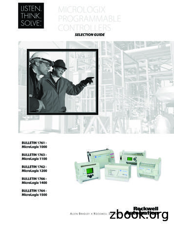
MicroLogix Programmable Controllers Overview 9 MicroLogix 1400 Controller The MicroLogix 1400 controller is our newest family of controllers to join the popular MicroLogix 1000, MicroLogix 1100, MicroLogix 1200, and MicroLogix 1500 controllers, and is designed to broaden appli
MicroLogix Programmable Controllers Overview 9 MicroLogix 1400 Controller The MicroLogix 1400 controller is our newest family of controllers to join the popular MicroLogix 1000, MicroLogix 1100, MicroLogix 1200, and MicroLogix 1500 controllers, and is designed to broaden appli
MicroLogix MicroLogix 1000 MicroLogix 1100 MicroLogix 1200 MicroLogix 1500 1761-NET-ENI Setting Example 6 (page 18) MicroLogix 1100 CPU Direct (channel1) Setting Example 7 (page 20) CompactLogix All CPUs that support the link I/F on the right 1761-NET-ENI Setting Example 5 (page 16) Al
MicroLogix/SLC family, the MicroLogix 1200 features an instruction set that is compatible with other MicroLogix controllers as well as SLC 500 controllers. That means that programs written for the MicroLogix 1000, MicroLogix 1500 or SLC 500 can be easily scaled for the MicroLogix 1200. Likewise, the
Manual 1763-UM001 A more detailed description of how to install and use your MicroLogix 1100 programmable controller and expansion I/O system. MicroLogix 1100 Instruction Set Reference Manual1763-RM001 A reference manual that contains data and function files, instruction set, and troubleshooting information for MicroLogix 1100.
install and use your MicroLogix 1500 programmable controller. MicroLogix 1500 Programmable Controllers User Manual 1764-UM001A-US-P A reference manual that contains data and functin files, instruction set, and troubleshooting information for MicroLogix 1200 and MicroLogix 1500. MicroLogix 1200 and MicroLog
Rem 1100 Notes_ Rev with Pix of Disassembly.doc 01/21/06 Page 2. REMINGTON 1100 – AN INTRODUCTION The Remington 1100 shotgun was introduced in 1965 as a 12-gauge semi-automatic. Since that introduction, the 1100 has been manufactured in many different gauges and configurations. It is usedFile Size: 409KBPage Count: 39Explore furtherRemington 1100 Owner’s Manual Download (PDF)www.rem870.comRemington 1100 Parts List Schematic Numrichwww.gunpartscorp.comRemington 1100, 1100 Special Field Schematic W/ Parts List .www.gunpartscorp.comRemington 1100 Shotgun Parts for sale eBaywww.ebay.comRemington 1100 Full Disassembly - YouTubewww.youtube.comRecommended to you based on what's popular Feedback
the instructional use of small groups so that students work together to maximize their own and each other's learning. It may be contrasted with competitive (students work against each other to achieve an academic goal such as a grade of "A" that only one or a few students can attain) and individualistic (students work by themselves to accomplish learning goals unrelated to those of the other .


