Waterproof Hd Action Camera Medion-PDF Free Download
2-9V in unit & 2 AA in camera. Match polarities ( ) and ( ). Set camera date back, close camera lens and connect plug to camera port. 2 3 Secure camera, open camera shutter, and slide unit power switch to (ON) and back to (OFF), then push camera test button. Close camera Shutter, remove camera & load film, connect plug to camera, close cover. 4
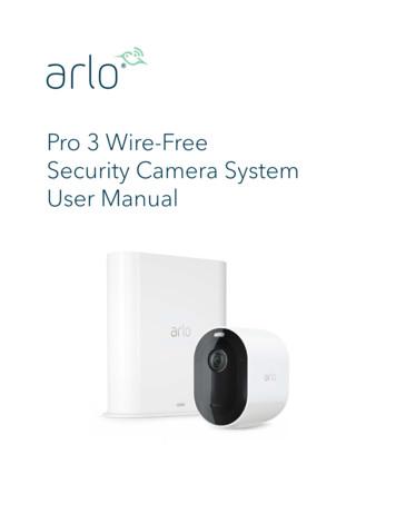
User Manual Replace a Pro 3 Camera battery You can leave the camera housing in place so the camera position stays the same. 1. Release the camera from the camera housing. Press the button on the charging port underneath the camera. The camera clicks as it disengages from the camera housing. 2. Pull the camera all the way out of the camera .
Waterproof Ultrasonic Distance Measuring Controller 一. Description: Waterproof ultrasonic distance measuring controller of DYP-A01Y -V2.0 uses the integrated and enclosed waterproof ultrasonic transducer, which has a certain dust waterproof level, suitable for the wet and poor measurement occasion. It is with a
G ra fik k a rte m it TV -O u t A n sch l sse n b e r S ca rt, S -V id e o o d e r Composite. Superschneller GDDR3 Speicher mit 900MHz. A TI X 7 4 0 X L G ra fik p ro ze sso r m it 4 2 5 M H z. PCI-Express x16 Bus-Konzept. eingebaute Tunerkarte mit analog Stereo-TV & FM Radio-Tuner WESTERN DIGITAL MEDION MEDION FIREWIRE
remote network video surveillance system, including wired IP bullet camera, wireless IP bullet camera, IP IR dome camera, IP IR waterproof camera, IP Pan/Tilt/Zoom Camera etc. We adopt high performance chip to ensure high quality media processor which processes audio and video collection, compression and transmission. Standard M-JPEG compression
than the action camera’s provided charging cable. Do not disassemble this action camera or attempt to repair or modify it in any manner. Be cautious of excessive drops, bumps, abrasions or other impacts to this action camera. If there is any damage to the action camera
Camera CCH-01G Jeep Grand Cherokee Camera CMB-16G Mercedes Benz GLK Trunk Handle Camera CCH-01S Jeep Wrangler Spare Tire Mount Camera CVW-07L VW Beetle License Plate Light Camera (LED) CVW-07G VW Beetle License Plate Light Camera CFD-03F Ford Tailgate Handle Camera CCH-01W Jeep Wrangler License Plate Light Camera CBM-01T BMW 5 Series Trunk .
1. Place the outdoor mount and secure it with screws. For drywall, use the wall anchors we provide. 2. Release the camera from the camera housing. Press the button on the charging port underneath the camera. The camera clicks as it disengages from the camera housing. 3. Pull the camera all the way out of the camera housing. 4.
On power-up, the camera interface board will read the SW1 DIP switches and set the camera video mode accordingly. If the DIP switches are set for 'Default Camera Mode' then the camera (and camera interface . Serial Camera Control The camera may be controlled by serial VISCA commands (J3). The VISCA serial signal is routed through the .
activities such as syncing the camera and updating the camera firmware. See the following table for explanations for the Camera LED. Camera LED Color and Action Meaning Solid blue The camera is connected to the Quick Charge 9v power adapter and is fully charged. Fast blinking blue for 3 seconds The camera is connected to the Quick Charge 9v power
2 Installation Guide Introduction Product overview This is the installation guide for TruVision Series 4 IP camera models: TVC-5401 (2MPX IP box camera) TVC-5402 (3MPX IP box camera) TVC-5403 (5MPX IP box camera) TVB-5401 (2MPX IP bullet camera, 2.8 to 12 mm) TVB-5402 (2MPX IP bullet camera, 8 to 32 mm)
Viper Digital Cinematographic Camera Operator's Manual The Viper FilmStream Camera combines two different application concepts in a single camera. By selecting the operation mode, the camera operates either as a HD video camera or as a digital film camera. The digital film camera mode is known as the FilmStream mode. Using this manual
3.1.2 Camera/Vision Camera/Vision tab in the Ribbon Menu contains camera controls and is available only when MV module is installed and at least one camera is enabled in the settings. Camera/Vision tab, when two cameras are enabled In the Camera/Vision tab there are following tool groups: Selected Camera.
Get to Know Your Essential Series Camera 6 Arlo Essential Series ire-Free Camera User Manual Meet your Essential Camera Your camera includes an integrated battery that can’t be removed. Front view Rear view Bottom view Sync button Charging port cover Camera LED Screw mount hole Microphone Ambient light sensor Speaker Camera lens Weather resistant
Camera LED Light An integrated LED light is located in the main housing of the camera. The light switch is located on the right of the main housing which turns the light on and off. Rotating the Camera The camera automatically loads the last zoom and color setting depending on the rotation of the camera. 1 Self-view Camera rotated directly at user
f p r r r f p r r r r X Y rrZ X Y Z Ground plane Camera 3D world z Origin at world coordinate Camera Projection (Pure Rotation) X C 1 R W Coordinate transformation from world to camera: Camera World 3 C C W 3 ªº «» «» «» ¼ X X R X r r r r 1: world x axis seen from the camera coord. r1r2 r 3 r 2: world y axis seen from the camera .
camera after a specific period of time that your camera is left idle. The Auto Power Off settings can be set from the Auto Power Off settings menu. Changing Camera Mode Your camera has three main modes: 1) Photo Capture Mode - Use this mode to capture photos with your camera. 2) Video Capture Mode - Use this mode to capture videos with your camera.
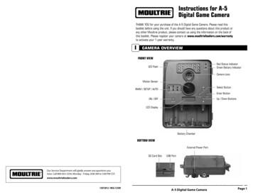
face the camera down the trail tilted at a slight downward angle. Face the camera North or South to avoid over exposure from the sun. Clear brush away from camera front to avoid false triggers from the wind. A-5 Digital Game Camera Page 9 Camera Setup Battery Installation Open the camera cover and install 4 C-Cell Alkaline batteries. Make sure .
5 Custom camera insert* 6 KODAK CRV3 Lithium Battery or equivalent** (not shown) 7 User's Guide or CD, Software CD, and Quick Start Guide (not shown) NOTE: *The custom camera insert perfectly fits your camera to the optional KODAK EASYSHARE Camera Dock II. DO NOT DISCARD. ** If your camera was packaged with a KODAK EASYSHARE Camera
3.2 Install USIM Card and Ethernet Cable 1. Screw the two screws on the waterproof cover. 2. Open the waterproof cover, and connect the Ethernet cable to the Ethernet interface. 3. Insert the USIM card to the USIM slot. Note following the directions. 4. Close the waterproof cover and tig
Pergo Portfolio WetProtect . Design layer Trend-forward decors in a variety of colors with an embossed surface texture. . This paintable waterproof molding is designed to cover the expansion space between the floor and the wall to provide a waterproof perimeter seal that adds
2. Waterproof receiver for wet conditions, only waterproof after the rubber cover is placed over charging jack. 3. Rechargeable collar and transmitter can be charged at the same time. 4. Rheostat dial that allows for gradual increases in stimulation intensity between 0-100 levels.
world of touch screens that's not so simple particularly when it comes to touch sensors. A better description might be "water resistant". Waterproof taken literally would mean the touch screen can operate reliably underwater for long periods of time. Waterproof displays or touch screen monitors refers to the sealing of the sensor face and
Figure 1 - Delco‐Remy standard three‐ unit waterproof regulator with cover removed. DIVISION OF GENERAL MOTORS CORPORATION, ANDERSON, INDIANA Delco‐Remy Standard Waterproof Post Type REGULATORS Service Bulletin 1R‐118A Pages: 8 Date 9‐1‐65 Supersedes Bulletin Dated 3‐15‐60
The Parkay XPR Laguna Collection brings a desirable rustic look and affordability. This 100% waterproof line presents a registered embossed finish over an XPR core. This makes it ideal for fast paced areas and light commercial projects. 30 12 WATERPROOF RIGID CORE. XPR STANDARDS WATERPROOF. Surface. Stone. XPS . flooring. # # # #
Camera to a Gateway via the Pulse Portal, is described on page 13. (3) The third method, which uses WPS to wirelessly enroll the HD Camera to an ADT Total Security (TS) Base panel via the TS Installer App, is described on page 17. Wired Connection to the Gateway Using the Pulse Portal 1. Set up the camera, as described in the previous chapter. 2.
Set the camera ID in OSD menu: System Camera Selector, ex: camera ID is set to 1. Then, press the “camera select” button “1” to control the camera. (3) Numeric Pad Use for setting the preset position 0 9. Press number button (0 9) to move the camera to pre-configure preset position 0 9.
Before Use 3 VQT0V83-If you see this symbol- Care of the camera Do not strongly shake or bump the camera. The camera may stop operating normally, pictures may not be recorded or the lens may be damaged. Retract the lens before carrying the camera. Retract the lens before playing back pictures. Sand or dust may cause the camera to
to select different camera modes, but can also be customized. To change the camera mode, swipe left or right and tap on the desired mode. To Rearrange Camera Modes press and move the modes according to personal preferences. You can even hide Camera Modes you rarely use. The Today Widget displays the first five camera modes. If you rearrange camera
This manual is applied to the following camera models: Type Model Dome camera A-42, A-44, A-44-OD, A-44-IR, A54 Mini Dome camera A-14, A-34, A-34W, A-46 Bullet Camera A-45 Mini Bullet Camera IV A-15, A-35 Also some basic information about the A-200 PTZ is in this manual for more detailed information please look at its separate manual.
Computer Vision for Active and Assisted Living 5 (a) Bullet type camera [34] (b) Pan-tilt-zoom camera [35] (c) Image from a night vision camera [36] (d) Image from a wearable camera (e) Image from a thermal camera [37] (f) Image from an omnidirectional camera Fig. 1 These figures show respectively different types of cameras and images.
digital camera and tighten it. Insert the other end into the trinocular port, adjust the CCD, and tighten it. 4.6.2.Assembly of the DSLR Camera Adapter and Digital SLR Camera Take away the dust-cover, screw one end of the DSLR camera adapter into the DSLR camera. Insert the other end of the camera adapter to the trinocular head, and tighten it.
Use the web browser to access and control the camera over the internet. Note: Any changes made to the camera’s configuration only apply to this camera. Change the administrator password once the set-up is complete. Only authorized users should be able to modify camera settings. To access the camera online: 1.
training. Responsibility for the safe operation of the vehicle remains with the driver at all times. The camera bracket is attached to the windshield, and the camera snaps into it. (See Section 3.1) Camera Lens Radar Sensor Camera Figure 1 – Bendix AutoVue FLC-20 Camera Figure
1 - cÂmera fotogrÁfica yashica dental eye iii; 1 - cÂmera fotogrÁfica yashica fund.kellog's fx-3 2000; 1 - cÂmera fotogrÁfica yashica fxd; 2 - cÂmera fotogrÁfica yashica fx-d quartz; 2 - cÂmera fotogrÁfica yashica fxd quartz; 1 - cÂmera fotogrÁfica yashika fx-d; 2 - carregador de baterias panasonic bq 345 a;
1 - cÂmera fotogrÁfica yashica dental eye iii; 1 - cÂmera fotogrÁfica yashica fund.kellog's fx-3 2000; 1 - cÂmera fotogrÁfica yashica fxd; 2 - cÂmera fotogrÁfica yashica fx-d quartz; 2 - cÂmera fotogrÁfica yashica fxd quartz; 1 - cÂmera fotogrÁfica yashika fx-d; 2 - carregador de baterias panasonic bq 345 a;
* If your camera was packaged with a Kodak EasyShare camera dock II, a Kodak EasyShare Ni-MH rechargeable battery and AC power adapter are included. For details, see page 61. 1 Camera 5 Custom camera dock insert (for EasyShare printer dock 4000 or EasyShare camera dock II) 2 CRV3 or equivalent* 6 Lens cap with strap 3 USB cable 7 Audio/Video cable
1. Click the Live view tab to navigate to the camera live view. 2. Click a camera to navigate to the live view of that camera. A blue dot after the camera name shows that continuous recording is in progress. A red dot after the camera name shows that motion detection recording is in progress. 3. Click to navigate from Live view to Recordings.
The chartplotter uses the Axis camera's default password to initially access the camera. When the chartplotter cannot connect to the camera because of mismatched passwords, the chartplotter displays a message that it cannot connect to the camera. When this message appears, you must reset your Axis camera password to its factory default settings.
Players of the camera module industry Image Sensors ( 1B) Modules Mfg ( 1B) Lens ( 1B) 2.5B 2.1B 1.7B 2.4B 1.4B 1.2B 1.1B 1.2B 1.5B Eight companies beyond US 1B (Yole Développement, August 2015) Market trend of mobile camera module Rear smartphone camera module Front smartphone camera module Wafer level camera module 10x10mm


